Introduction
The configuration of a bombe is carried out in several stages:
- Setting up drums
- Plugging the bombe
- Setting switches …
Setting up drums
Extract from the US 6812 Bombe Report:The first step in setting up a menu on a bombe is to insert the proper wheels in the enigmas. To assist in this operation the following color code for painting the wheels is used:
- I (1) – Red
- II (2) – Maroon
- III (3) – Green
- IV (4) – Yellow
- V (5) – Light Brown
- VI (6) – Blue
- VII (7) – Black
- VIII (8) – Silver
Plugging the bombe
The next step is the plugging of the bombe. Certain general rules have been adopted for plugging. On outside links the inner end of enigma is patched to the outlying letter. The following menu will be used to illustrate plugging. For instruction in plugging this menu see the representation of the jack panel in the rear of the bombe. There are 7 steps to be followed in plugging up a bombe as follows.- 1. Obtain menu.
- 2. Number-up menu to reduce nomber of commons used.
- 2a. Plug commoning plug into enigma jacks
- 3. Plugs enigmas to commons.
- 4. Patch commons to diagonal board, also patch input.
- 5. Count the letters plugged on the diagonal board and compare count this with the menu.
- 6. Count the number of plugs in the commons. Never should be less than 3. Compare this result between banks.
- 7. Compare commoning jack position in enigmas between banks.
Setting switches …
After the drums have been attached and the plugging finished, the next step is to set the switchs controlling the chain to be used, the letter at which searching is to be done, and the type of input; single or double. These switches are located in a panel on the right hand end of the bombe as see, from the front. There are four columns of toggle switches. At the top of the first column, is a switch labelled “chain 1, OFF-ON”. There are similar switches at the top of each other columns for chain 2 and 3. In each column below the chain switch are 26 searching switches labelled and reading downwards from Z to A. At the bottom of the second column is the CARRY OFF-ON switch. On the 30 point machine there is a DOUBLE INPUT, OFF-ON switch at the bottom of the fourth column. At the bottom of the third column is the CARRY HOME, OFF-ON switch. On the older 39 point bombe the setting of the machine for the type of input is accomplished by the insertion of a single or double input plugboard. The receptacle for this plugboard is located on the left hand end of the machine as seen from the front.
Start the bombe
- The CARRY and CARRY HOME switches must be OFF.
- Operate the MOTOR and CONTROL switches (the MOTOR switch is at the left and the CONTROL switch is at the right as you face the bombe).
- Depress the START key (the START key is at the right as you face the bombe)/
- Operate the CARRY switch when the bombe has attained its normal running speed.
Procedure when bombe stops
Whenever th bombe has found a possible solution it stops. A definitive procedure should be used in obtaining the information from the stop and restarting the bombe as follows:- 1. Bombe slows down and stops automatically.
- 2. On or more relays fall on indicator on the side of the machine.
- 3. Check the relay by lifting the bail lever. If the relay does not fall again call a technician.
- 4. Note on which chain the relay fell and record mentally.
- 5. Note the settings of the indicator drums.
- 6. Write in the appropriate column on the job sheet the readings you have taken from the drums and correspondingly the relay that has fallen in the columns for this reading.
- 7. To restart the bombe:
- a. Press the start key.
- b. Then lift the Bli lever
DO NOT PERFORM THESE TWO OPERATIONS SIMULTANEOUS.
- The stop number (example: 1)
- The name of the bombe (example: Agnes)
- The relative ringstellung (example: OHO)
- The stecker of the input letter (example: E)
- The wheel order (example: 143)
Example
Menu
We are going to take a simplified version of menu for the light blue network (menu 1).
Menu 1              Menu 2
======              ======
abcd efgh ijkl mnop qrst uvwx yz
================================
NACH RICH TENF UEHR ERVO RLEG EN   zz
kwtj xusv xutl kxge gwgg niiv ct
 *   *              **** *

XWEG ENVE RRAT DERT AKTI SCHE MG   za
itjm iiqn muea fthc xhkz xryw ze
**                  **

LIED ERUN GEND UERF ENAU FKEI NE   zb
rlti btmt ohen dqiw whxv ocve uw
  *                 **** *

MFUN KNET ZBEI UNWI CHTI GEMV ER   zc
njev izbv jooc etrc jlrl ybjz lz
     *              *

KEHR ALLE FUNK STEL LENG ERUF EN   zd
egpx tiyc owka bgzs fxgq vxwu lr
*  * *              **** *

                   zce   zaa   zze 1
                 K-----I-----x=====R
                 |  4 /   3    zdd
              zda|   /zae       2
                5|  /
                 | /10
                 |/
                 E   <<---- Input Letter
                 |6
              zbc|
                 | zde 9
                 T------A
                 7\    /8
                zab\  /zzb
                    \/
                    W
Setting the drums
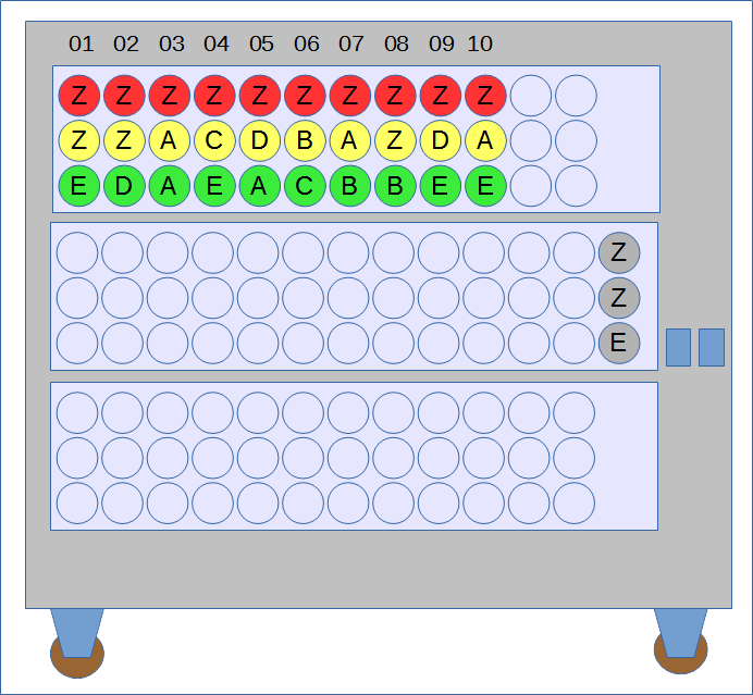
In the figure below, we have presented the positioning of the drums as well as their starting position. We have set the indicator drums (not associated with an Enigma) to the position of the first Enigma.
On the menu, the numbered links correspond to Enigmas. The order of the wheels here is 143 (I-IV-III) and uses red, yellow and green drums respectively.
Plugging the bombe
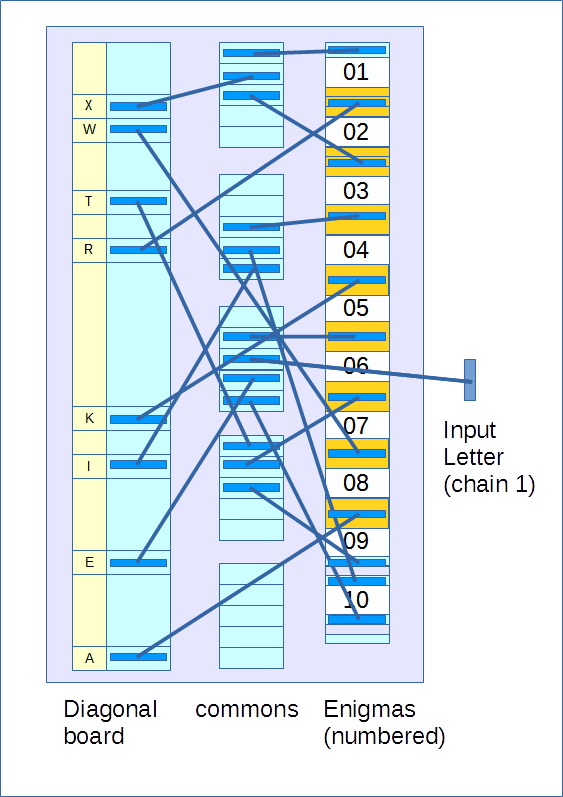
The rear of a bombe is made of jacks of three types: letters on the diagonal board, commons, and enigmas.
Plugging the bombe consists of reproducing the menu using cords ending at each end with plugs and inserting its plugs into the jacks (In the figure, the plugs are represented in navy blue).
First we link the enigmas together using the "commoning plugs". In the figure below, the commoning plugs are represented in orange. All engimas are linked together thanks to these plugs except enigma number 10. The commoning plugs have a jack which allows them to be connected either directly to the diagonal board or to a common.
Each common (there are 5 per bank), as their name suggests, connects the 5 jacks that compose it.
Each cord, plug, jack is composed of 26 wires which correspond to the 26 letters which themselves correspond to the clear or ciphered letters.