The concept of Rotor
Hebern's machines Home Page
- Hebern 1 rotor cipher machine
- The concept of Rotor (This Page)
- The mathematical vision of the machine
- A paper emulator
- An authentic message
- Cryptanalysis
- Simulator
- Utilities
- The Bible
(set of simple exercises) - Challenge
The concept of Rotor
During the First World War, several people invented the concept of rotor. This element will become the central element of most emerging encryption machines.
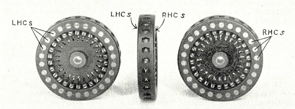
A rotor is a kind of puck having connectors on both sides. Each connector on one side is connected to another connector on the other side. All connections allow a permutation of an electric current, which if correctly designed can appear random. This permutation directs, for example, a current emitted when typing a letter on the typewriter keyboard towards a light panel on which a letter is displayed. If the rotor were static, the permutation would always be the same. The rotation of the rotor (hence its name) creates a new permutation. Around the edge of the rotor, there are the letters of the alphabet or a number, which makes it possible to identify the position of the rotor, in particular its initial position before encryption. Which corresponds to the essential configuration of the message key.
To increase the number of possible permutations, it is possible to use several rotors. In the case of the 1-rotor Hebern machine, only one rotor can be used at a time, but it can be chosen from a pool of rotors. Most encryption machines using rotors use several rotors at the same time: an electric current successively passes through several rotors starting from the keyboard until reaching the output equipment: printer or light panel.
Figure 1 shows a rotor from a Hebern 5-rotors machine.
| Fig 1: A rotor from a Hebern 5-rotors cipher machine |
Invention of the rotor
Several people invented independently the concept of rotor during the World War I:
- Edward Hebern (USA, 1917, patent: March 31, 1921)
- Hugo Koch (Netherlands, patent: October 7, 1919)
- Arthus Scherbius (Germany, patent: February 23, 1918)
Notes:
- Arvid Gerhard Dam invented an half-rotor which equipped (in 1925) Hagelin's B-21 machine. He patented his rotor the October 7, 1919.
- Scherbius bought the Koch's patent in 1927 (To avoid legal problems). However, no machine was built based on Koch's patent.
- Scherbius's rotors fitted the commercial Enigma A (with four rotors) of 1923.
Cipher machines equipped with rotors
On the website of Crypto Museum, you can see photos and descriptions of several cipher machines equipped with rotors.
Here is a (non-exhaustive) list of rotor machines:
- German: Enigma (many models),
- American: Hebern's machines with 1,3,5 rotors, M-134, Sigaba, M-325 Sigfoy, SIGCUM (or converter M-228), KL-7 Adonis
- British: Typex, Portex, Singlet,
- Russian: M-125 Fialka, T-205 Wecha, M-130 Korall
- Swiss: Nema, HX-63 (Hagelin Grypto-AG),
- Italian: OMI,
- Polish: Lacida,
Use a table to represent a rotor
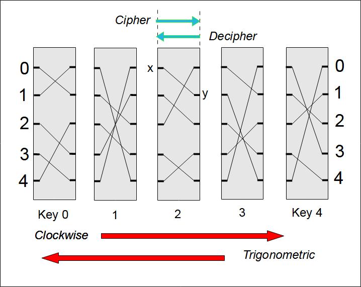
It is possible to represent a rotor using a table resembling to a Vigenère table.
To illustrate the concept of Rotor, we will describe a rotor composed of only 5 connectors, numbered from 0 to 4. Hebern's rotor (and that of Scherbius) was composed of 26 connectors to swap the 26 letters of the alphabet. The Russian Fialka cipher machine used 10 rotors simultaneously, each rotor having 30 connectors corresponding to the main letters of the Cyrillic alphabet (which is actually made up of 33 letters). The 1942 version of the B-211 machine was equipped (among other things) with rotors with 5 connectors, as in the example which follows.
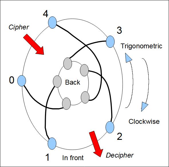
Figure 2 shows a flat rotor. We have shown the connectors on both sides and wiring. Figure 4 shows a rotor on edge with the wiring as it would appear for all rotor positions (initial position and after each rotation of a letter). Figure 3 is identical to Figure 2, but the rotor has been positioned upside down: the top right side becomes the bottom side. In the case of the Hebern rotor, we can see that the rotor is upside down because the letters which identify the position of the rotor are then upside down.
The following tables allow you to carry out encryption and decryption operations manually.
Table PCC       Table PCD      Table PTC       Table PTD     Table PTCr
  0 1 2 3 4      0 1 2 3 4      0 1 2 3 4      0 1 2 3 4      0 1 2 3 4
0 1 0 3 4 2    0 1 0 4 2 3    0 1 0 3 4 2    0 1 0 4 2 3    0 1 0 3 4 2
1 4 2 3 1 0    1 4 3 1 2 0    4 3 2 1 4 0    4 4 2 1 0 3    1 3 2 1 4 0
2 1 2 0 4 3    2 2 0 1 4 3    3 1 4 3 2 0    3 4 0 3 2 1    2 1 4 3 2 0
3 1 4 3 2 0    3 4 0 3 2 1    2 1 2 0 4 3    2 2 0 1 4 3    3 1 2 0 4 3
4 3 2 1 4 0    4 4 2 1 0 3    1 4 2 3 1 0    1 4 3 1 2 0    4 4 2 3 1 0

Table PICC     Table PICD      Table PITC     Table PITD    Table PICDr
  0 1 2 3 4      0 1 2 3 4      0 1 2 3 4      0 1 2 3 4      0 1 2 3 4
0 4 2 3 1 0    0 4 3 1 2 0    0 4 2 3 1 0    0 4 3 1 2 0    0 4 2 3 1 0
4 1 2 0 4 3    4 2 0 1 4 3    1 1 0 3 4 2    1 1 0 4 2 3    4 1 0 3 4 2
3 1 4 3 2 0    3 4 0 3 2 1    2 3 2 1 4 0    2 4 2 1 0 3    3 3 2 1 4 0
2 3 2 1 4 0    2 4 2 1 0 3    3 1 4 3 2 0    3 4 0 3 2 1    2 1 4 3 2 0
1 1 0 3 4 2    1 1 0 4 2 3    4 1 2 0 4 3    4 2 0 1 4 3    1 1 2 0 4 3
If we want to master the operation of the machine, we must specify everything :
- If the rotor moves clockwise or in the opposite way. It depends on which side you look at the machine.
- If the rotor input connectors are numbered clockwise or not.
- In what direction are the marks on the rim of the rotor.
 |
 |
The PCC table: PI, clockwise, cipher mode
The PCC (PI,clockwise,cipher) table should be used when the rotor moves clockwise. This direction is defined as follows: we look at the rotor flat from the side where the electric current comes from. In the case of the Hebern 1 rotor machine, we therefore place ourselves on the right side. On the other hand, in the case of the Hebern 5 rotors machine, the current comes from the left, so we place ourselves on the left of the machine.
Notes:
- If you look at the machine the other way, the clockwise direction becomes the trigonometric direction. In terms of vocabulary, the trigonometric direction is equivalent to counterclockwise.
- The letters (here numbers) which are on the rim are in counterClockwise direction.
- In all examples given, the connectors are counterclockwise.
Vertical columns are called "basic cipher text sequences". Each corresponds to different cipherments of the same clear letter.
Note that the diagonals (from the left going up to the right) reproduce the sequence 0,1,2,3,4 or part of this sequence. If we use the letters of the alphabet instead of numbers, the diagonals will reproduce the alphabet: a,b,c,d,..,z.
Encryption Example:
we want to encrypt message 13 with key 2. Before encryption, the key
changes to 3. The 1 is encrypted into 4 (intersection of line number
3 and column number 1). Then the rotor turns and the key becomes 4,
the 3 is encrypted as 4 (intersection of line number 4 and column
number 3).
The encrypted message is therefore 44.
The PCD table: PI, clockwise direction, decryption mode
The PCD table (PI, clockwise, decrypt), must be used when using the rotor in decrypt mode. The current flows in the opposite direction: left to right instead of right to left and the rotor appears to rotate in a trigonometric direction.
The other tables ...
- The PTC table (PI, trigonometric sense, cipher mode) must be used when the rotor advances in the trigonometric direction. We notice that the diagonals (from the left going down towards the right) reproduce the sequence 0,1,2,3,4.
- The PTD table (PI, trigonometric sense, decryption mode) must be used when using the rotor in decryption mode when it advances in trigonometric sense.
- The PTCr table (PI, trigonometric sense, rim in clockwise direction) is identical to the PTC table except that the rim of the rotor is in clockwise direction.
-
The following 4 tables (PICC, PICD, PITC, PITD, PITCr) correspond
to the previous tables in the case where the rotor is reversed (we
put it in the other direction, the letters appear upside down).
Note: The ability to reverse a rotor is not possible on all encryption machines. So, on the Enigma, this is not possible. On the other hand, it is possible on the Typex although it derives from the Enigma as well as on all American rotor machines. This is a legacy of the machines designed by Hebern.
 |
 |
Using a Permutation Table to Represent a Rotor
Introduction
A first mathematical way of representing a rotor is to memorize its wiring in a table (called PI). The index specifies the input connector number, the associated value corresponds to the output connector number.
Note: a mathematical representation is mandatory if you want to emulate the operation of a rotor using a computer program.
If we want to simulate the operation of a rotor, there is no need to provide a complete table. The first row of the table is enough. We call this line PI. This is simply the wiring from the rotor at key 0. The other rows in the table are easily deduced from PI and the key.
Clockwise encryption
Let x be the plain letter, y be the ciphered letter, i be the key and PI be the table of connections to key 0. The following formula connects these elements:
y = (PI[ (x + i )mod 5] – i)mod 5 and PI = [1, 0, 3, 4, 2]
The operation “mod” means Modulo (the remainder of integer division). Thus, if we are at key 0 and we move backwards, the key becomes 4. On the other hand, if we are at key 4 and we move forward, the key becomes 0. If we consider Modulo operations as implicit, the formula simplifies:
y = PI[ x + i ] - i and PI = [1, 0, 3, 4, 2]If i is equal to 0, we have:
y = PI[ x ]
In fact this is the definition of PI.
Let's return to our encryption example: encrypt message 13 with key 2 (actually 3, because the rotor advances before encryption):
	y = PI[ 1 + 3 ] - 3 = 2 – 3 = -1 (mod 5) = 4
 	y = PI[ 3 + 4 ] - 4 = PI[ 2 ] - 4 = 3 – 4 = -1 = 4
Encryption in the trigonometric direction
Encryption in the trigonometric direction:
y = PI[ x - i ] + i and PI = [1, 0, 3, 4, 2]If we return to the previous encryption example, 13 at key 2 (actually 3) gives 21.
Decryption
In decryption mode (Reverse), you must calculate PI_inverse. PI and PI_inverse are linked by the formula:
PI . PI_inverse = I
I being the "identity" permutation, that is to say the permutation that nothing permutes: [0,1,2,3,4]: connector 0 is connected to connector 0, connector 1 is connected to connector 1, etc...
Let's calculate PI_inverse:
	y = PI[ x + 1 ] - i
	x =  PI_inverse[ y + i ] - i
  Then:
	y – x = PI[ x + i ] - PI_inverse[ y – i ]
  Then, if i = 0,
	PI-1[ y ] = PI[ x ] - ( y – x )
  If x = 0,  PI_inverse[ 1 ]  = PI[ 0 ] - ( 1 – 0) = 1 – 1  = 0
  If x = 1,  PI_inverse[ 0 ]  = PI[ 1 ] - ( 0 – 1 ) = 0 + 1 = 1
  If x = 2,  PI_inverse[ 3 ]  = PI[ 2 ] - ( 3 – 2 ) = 3 – 1 = 2
  If x = 3,  PI_inverse[ 4 ]  = PI[ 3 ] - ( 4 – 3 ) = 4 – 1 = 3
  If x = 4,  PI_inverse[ 2 ]  = PI[ 4 ] - ( 2 – 4 ) = 2 + 2 = 4
  Then PI_inverse = [1, 0, 4, 2, 3]

  We also have the relationship:
	y = PI[ x ]   and PI_inverse[ y ] = x
A reciprocal permutation
A PI permutation can be reciprocal. In this case, decryption and encryption are carried out in the same way without having to reverse the direction of the electrical circuit. In this case, PI and PI_inverse are identical.
  If (with the key 0)
	y = PI[x]  and  PI = PI_inverse
  Then
	x = PI[y]

  Example:
	PI = [3, 4, 2, 0, 1 ]
  We then have:
	PI[0] = 3 and PI[3] = 0
	PI[1] = 4 and PI[4] = 1
	PI[2] = 2 and PI[2] = 2
	PI[3] = 0 and PI[0] = 3
	PI[4] = 1 and PI[1] = 4

  And here are the encryption and decryption tables:

Table PCC       Table PCD
  0 1 2 3 4       0 1 2 3 4
0 3 4 2 0 1     0 3 4 2 0 1
1 3 1 4 0 2     1 3 1 4 0 2
2 0 3 4 1 2     1 3 1 4 0 2
3 2 3 0 1 4     3 2 3 0 1 4
4 2 4 0 3 1     4 2 4 0 3 1
If we encrypt 13 at key 2 (therefore at effective key 3), we obtain 33. If we decipher 33 with key 2 with THE SAME TABLE, we obtain 13!
Using an offset table to represent a rotor
There is a mathematical representation of a rotor which reproduces more clearly its wiring and therefore the invariant aspect of it when the rotor turns: these are the offsets. For example, in encryption mode, if connector 0 is connected to connector 1, we have an offset of 1 (0+1=1). This is an invariant. Indeed, if we turn the rotor in the trigonometric direction, connector 4 will be connected to connector 0, which corresponds to the same offset of 1 (4+1=5=0).
Here are the previous mathematical formulas rewritten using Shifts:
Calculate the table of shifts (D):
We have, by definition:	D[ x ] = y – x
Then
	D = [ 1-0, 0-1, 3-2, 4-3, 2-4 ] = [1, 4, 1, 1, 3]

Clockwise direction:
	y = PI[ x + i ]  - i    and   PI = [1, 0, 3, 4, 2]
	y = x + D[ x + i ]     and    D  = [1, 4, 1, 1, 3]

In the trigonometric sense:
	y = PI[ x - i ]  + i     and  PI = [1, 0, 3, 4, 2]
	y = x + D[ x – i ]	and   D  = [1, 4, 1, 1, 3]
The offset D_inverse which corresponds to the decryption mode (reverse) is linked to the offset in the mode where the rotor is reversed is given by the following formula:
D_inverse[ y ] = -D[ x ]
Note: if we look at the PCC table, the first column corresponds to the offsets.
We can recreate the previous tables using the offsets rather than the PI table (SCC: Shift, clockwise, cipher mode).
Table SCC       Table SCD       Table STC       Table STD
  0 1 2 3 4       0 1 2 3 4       0 1 2 3 4       0 1 2 3 4
0 1 4 1 1 3     0 1 4 2 4 4     0 1 4 1 1 3     0 1 4 2 4 4
1 4 1 1 3 1     1 4 2 4 4 1     4 3 1 4 1 1     4 4 1 4 2 4
2 1 1 3 1 4     2 2 4 4 1 4     3 1 3 1 4 1     3 4 4 1 4 2
3 1 3 1 4 1     3 4 4 1 4 2     2 1 1 3 1 4     2 2 4 4 1 4
4 3 1 4 1 1     4 4 1 4 2 4     1 4 1 1 3 1     1 4 2 4 4 1

Table SICC      Table SICD      Table SITC      Table SITD
  0 1 2 3 4       0 1 2 3 4       0 1 2 3 4       0 1 2 3 4
0 4 1 1 3 1     0 4 2 4 4 1     0 4 1 1 3 1     0 4 2 4 4 1
4 1 1 3 1 4     4 2 4 4 1 4     1 1 4 1 1 3     1 1 4 2 4 4
3 1 3 1 4 1     3 4 4 1 4 2     2 3 1 4 1 1     2 4 1 4 2 4
2 3 1 4 1 1     2 4 1 4 2 4     3 1 3 1 4 1     3 4 4 1 4 2
1 1 4 1 1 3     1 1 4 2 4 4     4 1 1 3 1 4     4 2 4 4 1 4
The permutations
Introduction
From a mathematical point of view, the operation of a rotor belongs to the domain of permutations (see References and Web links below). So, to better understand how rotors work, we will briefly review this branch of mathematics.
Mathematical notation of permutations
Mathematicians mainly use three notations (see Wikipedia) to represent a permutation. I have added, for the sake of completeness, the matrix form.
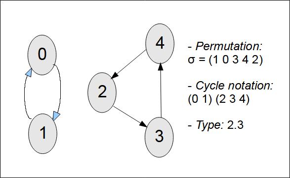
Given the set S = {0, 1, 2, 3, 4}, we can permute the elements, such that
\( \sigma(0) = 1, \sigma(1) = 0, \sigma(2) = 3, \sigma(3) = 4, \sigma(4) = 2 \)
- Two-line notation
\( \sigma = \begin{pmatrix}0 & 1 & 2 & 3 & 4 \\1 & 0 & 3 & 4 & 2\end{pmatrix} \) - One-line notation
If the elements to be permuted follow in an obvious order (0,1,2, ..., 1,2,3, ..., a,b,c, ...), we can omit the first line:
\( \sigma = \begin{pmatrix}1 & 0 & 3 & 4 & 2 \end{pmatrix} \) - Cycle notation
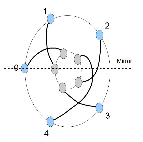
\( \sigma = (0 \space 1)(2 \space 3 \space 4) \)The cycle notation describes the effect of repeatedly applying the permutation on the elements of the set: 0 gives 1, 1 gives 0, this closes the first cycle. Then 2 gives 3, 3 gives 4, 4 gives 2, this closes the second cycle. Figure 5 shows this cycle.
A cycle of length 1 corresponds to a identity. A cycle of length 2 is called a transposition. The type of a permutation gives the length of its components, for example 2.3 (for the permutation (0 1)(2 3 4)).
When elements are not permuted, they can be omitted, including when indicating cycles.
\( \sigma = \begin{pmatrix}1 & 0 & 3 & 4 & 2 & 5 \end{pmatrix} = (0 \space 1)(2 \space 3 \space 4) (5)) = (0 \space 1)(2 \space 3 \space 4) \)
The type 1.2.3 = 3.2.1 = Type 2.3 = Type 3.2. - Matrix notation
A permutation matrix is an n × n matrix that has exactly one entry 1 in each column and in each row, and all other entries are 0. The value n is the size of a permutation (5 in the example).
\( \sigma(0,1,2,3,4) = (1,0,3,4,2) \quad \text{ the matrix equivalent is } \quad \begin{pmatrix} 0 & 1 & 0 & 0 & 0 \\ 1 & 0 & 0 & 0 & 0 \\ 0 & 0 & 0 & 1 & 0 \\ 0 & 0 & 0 & 0 & 1 \\ 0 & 0 & 1 & 0 & 0 \end{pmatrix} \)
The notations I use in my Web pages
In fact, strictly speaking, I do not use any of the previous notations. The two-line
notation is certainly the most readable but it is the most complex for a Web page
designer: you have to master the layout and also Latex. I mainly use a notation
inspired by the one-line notation except that I separate the permuted elements with
commas instead of spaces (spaces are difficult to handle in Latex).
\(
\sigma = (1, 0, 3, 4, 2)
\)
I also use a notation close to that of cycles, (in this case, I only put commas if
necessary), but to avoid confusion with the previous notation, I put parentheses
around the cycles:
\(
\sigma = ((0 \space 1)(2 \space 3 \space 4))
\)
In short, as you can see, I am mainly inspired by the permutation notation used by the python library Sympy (see below). It's a bit logical for a computer scientist ;-).
Here are some examples:
	sigma = (1, 0, 3, 4, 2, 5) = ((0,1),(2,3,4),(5)) = ((0 1)(2 3 4))
        identity = (0, 1, 2, 3, 4, 5) = (())
	rotation = (1, 2, 3, 4, 5, 0) = ((0, 1, 2, 3, 4, 5))
Cardinality
The cardinality of a composition corresponds to the possible number of permutations. It is directly related to the size of the set of elements that undergo the permutation.
Let N values be permuted, the cardinality is equal to N! (factorial N). So if we manipulate 5 values, we have at most 120 permutations.
Compositions of permutations
The products of permutations is called composition.
Notation: \( \sigma \cdot \pi = \sigma(\pi(x)) \)
Notes:
- The dot is not the only operator used. We also find (in articles dealing with permutations) a small circle or even the star (*).
- We can omit the composition operator, it is implicit.
The composition is associative: \( (\sigma\pi)\tau = \sigma(\pi\tau) \)
Example of composition with matrices:
\(
\begin{pmatrix} 3 \\ 1 \\ 4 \\ 0 \\ 2 \end{pmatrix} =
\begin{pmatrix}
0 & 0 & 1 & 0 & 0 \\
1 & 0 & 0 & 0 & 0 \\
0 & 0 & 0 & 1 & 0 \\
0 & 1 & 0 & 0 & 0 \\
0 & 0 & 0 & 0 & 1
\end{pmatrix}
\begin{pmatrix}
0 & 1 & 0 & 0 & 0 \\
1 & 0 & 0 & 0 & 0 \\
0 & 0 & 0 & 1 & 0 \\
0 & 0 & 0 & 0 & 1 \\
0 & 0 & 1 & 0 & 0
\end{pmatrix}
\begin{pmatrix} 0 \\ 1 \\ 2 \\ 3 \\ 4 \end{pmatrix}
\)
\(
\begin{pmatrix} 3 \\ 1 \\ 4 \\ 0 \\ 2 \end{pmatrix} =
\begin{pmatrix}
0 & 0 & 0 & 1 & 0 \\
0 & 1 & 0 & 0 & 0 \\
0 & 0 & 0 & 0 & 1 \\
1 & 0 & 0 & 0 & 0 \\
0 & 0 & 1 & 0 & 0
\end{pmatrix}
\begin{pmatrix} 0 \\ 1 \\ 2 \\ 3 \\ 4 \end{pmatrix}
\)
Power operator and order of a permutation
A permutation raised to the power of three corresponds to composing the permutation three times with itself
\( \pi^{3} = \pi \cdot \pi \cdot \pi \)
If we raise a permutation to the power N which gives the identity permutation, N is called the order of the permutation.
Reverse permutation
For each permutation, there exists an inverse permutation, such that the composition of the permutation and its inverse permutation gives the identity permutation.
\( x = (0,1,2,3,4) \)
\( I = (0,1,2,3,4) \)
\( \pi(x) = (1,0,3,4,2) \)
\( \pi^{-1}(x) = (1,0,4,2,3) \)
\( \pi \cdot \pi^{-1} = \pi^{-1} \cdot \pi = I \)
\( (\sigma \cdot \pi)^{-1} = \pi^{-1} \cdot \sigma^{-1} \)
\( (\alpha \cdot \beta \cdot \gamma )^{-1} = \gamma^{-1} \cdot
\beta^{-1} \cdot \alpha^{-1} \)
Transposition
A transposition is a cycle of length 2. So, in cycle notation, a transposition has the form (0 1). Each transposition is its own inverse.
Since every permutation is a product of cycles, every permutation may be represented as a product of transpositions.
\( x = (0, 1) \)
\( \pi(x) = (1, 0) \)
\( \pi^{-1}(x) = (1, 0) \)
\( \pi = \pi^{-1} \)
\( (0,1) (1,0) = I \)
\( \pi \cdot \pi^{-1} = \pi^{-1} \cdot \pi = I \)
Involution
A permutation is an involution if and only if it can be broken down into disjoint cycles of lengths less than or equal to 2. It is thus exclusively made up of fixed points and transpositions.
If a permutation is the product of transpositions, it is an involution.
If a permutiation is an involution, the permutation is reciprocal.
\( \pi = \pi^{-1} \) and
\( \pi^2 = I \)
Example:
\( \pi = (1, 0, 3, 2, 4) \)
\( \pi^2 = (0=>1=>=0, 1=>0=>1, 2=>3=>2, 3=>2=>3, 4=>4=>4) = (0,1,2,3,4) = I \)
\( \pi = (0, 1) (2, 3) (4) \) Then Cycles: 2.2.1
Each permutation can be represented as a product of transpositions
For example: ((0,1)(2,3,4)) == ((0,1)) * ((2,3)) * ((2,4))Conjugating permutations
Consider a set S on which the \( \tau \text{ and } \sigma \) permutations are defined.
The two permutations are conjugate if there exists a permutation \( \pi \)
which corresponds to the following composition:
\( \tau = \pi \sigma \pi^{-1} \)
The Rejewski's Theorem: If two permutations have the same shape [or type] (in cycle notation), they are conjugate.
If alpha and beta are conjugate, the number of permutations that conjugate one
into the other is equal to
n = r1 * r2 * r3 * … * t1! * t2! * t3! * ...
r1, r2, r3,... corresponds to the length of the cycles and t1, t2, t3,...
to their number. For example:
alpha = ((a, b, c)(d, e, f)(g, h)(i)(j)(k))
n = (3 * 3 * 2 * 1 * 1 * 1) * (2! * 1! * 3!) = 18 * 12 = 216
Rotation of a rotor
The formula
Let C be the permutation (a Caesar substitution) which allows
the rotation of a rotor represented by the permutation R. Let
k be the key (the number of steps of advancement of the rotor),
then the complete composition is expressed in the form , if the
rotor advances clockwise:
\( \ \ \ \ \ C^{-k} \cdot R \cdot C^{k} \)
In the case where the rotor advances in the trigonometric direction:
\( \ \ \ \ \ C^{k} \cdot R \cdot C^{-k} \)
We can see that the rotation and the rotor are conjugated.
Example with permutation matrices
Let the following permutations be (Caesar substitution): \( C^1, \ C^2, \ C^3, \ C^4, \ C^5 = C^0 = I \)
\( \begin{pmatrix} 0 & 1 & 0 & 0 & 0 \\ 0 & 0 & 1 & 0 & 0 \\ 0 & 0 & 0 & 1 & 0 \\ 0 & 0 & 0 & 0 & 1 \\ 1 & 0 & 0 & 0 & 0 \end{pmatrix} \begin{pmatrix} 0 & 0 & 1 & 0 & 0 \\ 0 & 0 & 0 & 1 & 0 \\ 0 & 0 & 0 & 0 & 1 \\ 1 & 0 & 0 & 0 & 0 \\ 0 & 1 & 0 & 0 & 0 \end{pmatrix} \begin{pmatrix} 0 & 0 & 0 & 1 & 0 \\ 0 & 0 & 0 & 0 & 1 \\ 1 & 0 & 0 & 0 & 0 \\ 0 & 1 & 0 & 0 & 0 \\ 0 & 0 & 1 & 0 & 0 \end{pmatrix} \begin{pmatrix} 0 & 0 & 0 & 0 & 1 \\ 1 & 0 & 0 & 0 & 0 \\ 0 & 1 & 0 & 0 & 0 \\ 0 & 0 & 1 & 0 & 0 \\ 0 & 0 & 0 & 1 & 0 \end{pmatrix} \begin{pmatrix} 1 & 0 & 0 & 0 & 0 \\ 0 & 1 & 0 & 0 & 0 \\ 0 & 0 & 1 & 0 & 0 \\ 0 & 0 & 0 & 1 & 0 \\ 0 & 0 & 0 & 0 & 1 \end{pmatrix} \)
let's calculate \( C^{2} \cdot R \cdot C^{-2} \),
with \( R = (1,0,3,4,2) \)
\( C^{2} = C^{1} \cdot C^{1} = \begin{pmatrix} 0 & 1 & 0 & 0 & 0 \\ 0 & 0 & 1 & 0 & 0 \\ 0 & 0 & 0 & 1 & 0 \\ 0 & 0 & 0 & 0 & 1 \\ 1 & 0 & 0 & 0 & 0 \end{pmatrix} \cdot \begin{pmatrix} 0 & 1 & 0 & 0 & 0 \\ 0 & 0 & 1 & 0 & 0 \\ 0 & 0 & 0 & 1 & 0 \\ 0 & 0 & 0 & 0 & 1 \\ 1 & 0 & 0 & 0 & 0 \end{pmatrix} = \begin{pmatrix} 0 & 0 & 1 & 0 & 0 \\ 0 & 0 & 0 & 1 & 0 \\ 0 & 0 & 0 & 0 & 1 \\ 1 & 0 & 0 & 0 & 0 \\ 0 & 1 & 0 & 0 & 0 \end{pmatrix} = C^{2} \)
\( C^{-2} = C^{-1} \cdot C^{-1} = C^{5-1} \cdot C^{5-1} = C^{4} \cdot C^{4} = \begin{pmatrix} 0 & 0 & 0 & 0 & 1 \\ 1 & 0 & 0 & 0 & 0 \\ 0 & 1 & 0 & 0 & 0 \\ 0 & 0 & 1 & 0 & 0 \\ 0 & 0 & 0 & 1 & 0 \end{pmatrix} \cdot \begin{pmatrix} 0 & 0 & 0 & 0 & 1 \\ 1 & 0 & 0 & 0 & 0 \\ 0 & 1 & 0 & 0 & 0 \\ 0 & 0 & 1 & 0 & 0 \\ 0 & 0 & 0 & 1 & 0 \end{pmatrix} \)
\( C^{4} \cdot C^{4} = \begin{pmatrix} 0 & 0 & 0 & 1 & 0 \\ 0 & 0 & 0 & 0 & 1 \\ 1 & 0 & 0 & 0 & 0 \\ 0 & 1 & 0 & 0 & 0 \\ 0 & 0 & 1 & 0 & 0 \end{pmatrix} = C^{3} \)
\( C^{2} \cdot R \cdot C^{-2} = \begin{pmatrix} 0 & 0 & 1 & 0 & 0 \\ 0 & 0 & 0 & 1 & 0 \\ 0 & 0 & 0 & 0 & 1 \\ 1 & 0 & 0 & 0 & 0 \\ 0 & 1 & 0 & 0 & 0 \end{pmatrix} \cdot \begin{pmatrix} 0 & 1 & 0 & 0 & 0 \\ 1 & 0 & 0 & 0 & 0 \\ 0 & 0 & 0 & 1 & 0 \\ 0 & 0 & 0 & 0 & 1\\ 0 & 0 & 1 & 0 & 0 \end{pmatrix} \cdot \begin{pmatrix} 0 & 0 & 0 & 1 & 0 \\ 0 & 0 & 0 & 0 & 1 \\ 1 & 0 & 0 & 0 & 0 \\ 0 & 1 & 0 & 0 & 0 \\ 0 & 0 & 1 & 0 & 0 \end{pmatrix} = \begin{pmatrix} 0 & 1 & 0 & 0 & 0 \\ 0 & 0 & 1 & 0 & 0 \\ 1 & 0 & 0 & 0 & 0 \\ 0 & 0 & 0 & 0 & 1 \\ 0 & 0 & 0 & 1 & 0 \end{pmatrix} \)
Exemple:
\( ( C^{2} \cdot R \cdot C^{-2} ) \cdot (0, 1, 2, 3, 4) = \begin{pmatrix} 0 & 1 & 0 & 0 & 0 \\ 0 & 0 & 1 & 0 & 0 \\ 1 & 0 & 0 & 0 & 0 \\ 0 & 0 & 0 & 0 & 1 \\ 0 & 0 & 0 & 1 & 0 \end{pmatrix} \cdot \begin{pmatrix} 0 \\ 1 \\ 2 \\ 3 \\ 4 \end{pmatrix} = \begin{pmatrix} 1 \\ 2 \\ 0 \\ 4 \\ 3 \end{pmatrix} \)
Note: we can clearly see that we have the expected result (see the
third line of the PTC table).
Using the SymPy Python library
We have just studied permutations from a mathematical point of view.
The Python SymPy library allows us to implement this concept.
Load the SymPy library
C:\>python
Python 3.8.0 ...
...
>>> from sympy.combinatorics import Permutation
Create a Permutation (Instancing)
We can give as an argument to the constructor a permutation specified by the usual notation or by using a sequence of cycles.>>> sigma = Permutation([1,0,3,4,2]) >>> pi = Permutation([[0,1],[2,3],[4]]) >>> tau = Permutation([1,2,3,4,5,0])
Print a Permutation
Using the usual notation or in the form of a sequence of cycles (complete or not).>>> sigma.full_cyclic_form [[0, 1], [2, 3, 4]] >>> sigma.array_form [1, 0, 3, 4, 2] >>> pi.array_form [1, 0, 3, 2, 4] >>> pi.full_cyclic_form [[0, 1], [2, 3], [4]] >>> pi.cyclic_form [[0, 1], [2, 3]] >>> tau.cyclic_form [[0, 1, 2, 3, 4, 5]]
Cardinality, Size
>>> sigma.cardinality
120
>>> import math
>>> math.factorial(5)
120
>>> sigma.size
5
Composition of permutation (or product)
Composition consists of applying several permutations in sequence. Composition is associative. We can compare two permutations.>>> sigma_pi = sigma * pi >>> sigma_pi.array_form [0, 1, 2, 4, 3] >>> sigma_pi.full_cyclic_form [[0], [1], [2], [3, 4]] >>> >>> spt_1 = (sigma * pi) * tau >>> spt_2 = sigma * (pi * tau) >>> spt_1 == spt_2 True >>> spt_1.full_cyclic_form [[0, 1, 2, 3, 5], [4]]
The Identity permutation
>>> I = Permutation([0,1,2,3,4])
>>> I
Permutation(4)
>>> I.full_cyclic_form
[[0], [1], [2], [3], [4]]
>>> I.cyclic_form
[]
>>> I.array_form
[0, 1, 2, 3, 4]
>>> I.is_Identity
True
>>>
The reverse permutation
>>> ~sigma
Permutation(0, 1)(2, 4, 3)
>>> ~pi
Permutation(4)(0, 1)(2, 3)
>>> (~sigma * sigma) == I
True
>>>
>>> (~(sigma * pi)) == ((~pi) * (~sigma))
True
The power operator
>>> sigma**3 == sigma * sigma * sigma
True
>>> (sigma**3).full_cyclic_form
[[0, 1], [2], [3], [4]]
>>> sigma**5
Permutation(0, 1)(2, 4, 3)
>>> sigma**6		# the order of sigma is 6
Permutation(4)
>>> sigma.order()
6
Decompose a permutation into transpositions
>>> tau
Permutation(0, 1, 2, 3, 4, 5)
>>> tau.full_cyclic_form
[[0, 1, 2, 3, 4, 5]]
>>> tau.transpositions()
[(0, 5), (0, 4), (0, 3), (0, 2), (0, 1)]
>>> pi
Permutation(4)(0, 1)(2, 3)
>>> pi.transpositions()
[(0, 1), (2, 3)]
>>> sigma
Permutation(0, 1)(2, 3, 4)
>>> sigma.transpositions()
[(0, 1), (2, 4), (2, 3)]
Conjugation
The gamma and sigma permutations are conjugated, but the pi and sigma permutations are not.>>> gamma = Permutation([[0,5],[1,2,3]]) >>> >>> gamma == (tau * sigma * ~tau) True >>> >>> pi == (tau * sigma * ~tau) False
A software which emulates a Rotor
The following program emulates the operation of a rotor. The program is written in python.
C:\H1_TOOLS> type rt.py
# rt.py
pi = list(map(int,input("Rotor wiring ? ").split(",")))
plain = input("Plain text (to cipher) ? ")
key = int(input("Key ? "))

i = key
print("Cryptogram: ", end="")
for x in plain:
    x = int(x)
    i = (i + 1)%5
    y = (pi[ (x+i)%5 ] - i)%5
    print(y, end="")
print()

C:\H1_TOOLS> python rt.py
Rotor wiring ? 1,0,3,4,2
Plain text (to cipher) ? 13
Key ? 2
Cryptogram: 44
The software hebern1_tui.py emulates a Hebern 1 rotor cipher machine. The program is more complete and more realistic.
Miscellaneous
Rotor advancement before encryption
In all mechanical encryption machines using rotors, encryption (or decryption) is accomplished by establishing an electrical circuit. But first, pressing a key on the keyboard mechanically causes the advancement of one or more rotors.
On the other hand, in the case of an electric or electronic machine, using electrical relays, we can imagine that the advancement of the rotors is carried out before or after encryption.
The interval method for designing the wiring of a rotor
Not all permutations are cryptographically equivalent. Thus the worst being the Identity permutation: connector 0 of the input connected to connector 0 of the output, connector 1 of the input connected to connector 1 of the output, etc... Consequently, there is no permutation !
The best permutation corresponds to the one where each movement (Shift) is represented and of course in a random order (do not use 3,4,0,1,2 for example). If the number of connectors is odd, it is possible, if it is even, for example 26, a displacement must necessarily be present twice.
This method is called 'interval method'. It was invented by Hebern.
Twist and offset
Suppose that the two faces of the rotor are disjoint but that the connectors connect the two faces. It is possible to “twist” the rotor. Thus without touching the connections, the two faces will be shifted from one to several positions (cf. Figure 6). A cryptanalysis can very well decipher messages and reconstruct the wiring of the rotor but without knowing the twist and offset.
Likewise, a cryptanalyst may ignore the true position of the rotor start. This is why, in the absence of information, we will assume that the reference key will be set arbitrarily at Z.
| Fig 6: The twist phenomenon |
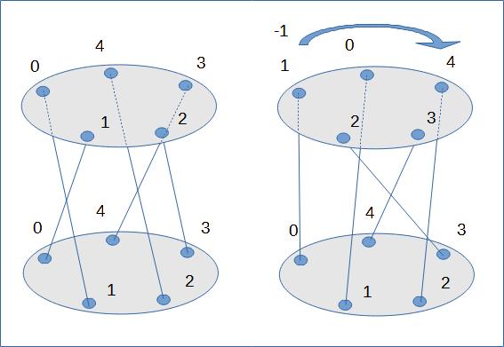
Table PCC      Table SCC      Table PCCt     Table SCCt    Table PCCt2
  0 1 2 3 4      0 1 2 3 4      0 1 2 3 4      0 1 2 3 4     0 1 2 3 4
0 1 0 3 4 2    0 1 4 1 1 3    0 0 3 4 2 1    0 0 2 2 4 2   0 2 1 0 3 4
1 4 2 3 1 0    1 4 1 1 3 0    1 2 3 1 0 4    1 2 2 4 2 0   1 0 4 2 3 1
2 1 2 0 4 3    2 1 1 3 1 4    2 2 0 4 3 1    2 2 4 2 0 2   2 3 1 2 0 4
3 1 4 3 2 0    3 1 3 1 4 1    3 4 3 2 0 1    3 4 2 0 2 2   3 0 1 4 3 2
4 3 2 1 4 0    4 3 1 4 1 1    4 2 1 4 0 3    4 2 0 2 2 4   4 0 3 2 1 4
The first two tables (PCC and SCC) respectively present an encryption table and the corresponding offsets. The following two tables (PCCt and SCCt) provide the same information but after a twist of -1 (the one presented in figure 6). The last table (PCCt2), present an encryption table but after a twist of +1.
Note: Note that the PCCt table is equivalent to the PCC table but shifted vertically by one position to the left (-1). The PCCt2 table, on the other hand, is shifted vertically by one position to the right (+1) in relation of the table PCC.
Here is the formula that allows you to calculate the offsets after a twist:
D_twist[i] = D[ i – twist ] - twist
Signature
Introduction
Problem: how to identify a rotor? Unfortunately, the wiring represented by the PI table is not the solution. Indeed, if we rotate a rotor, the same rotor is represented by a new PI table after rotation.
First solution: the permutation type
A first solution is to use the type (in the mathematical sense). So, for example, here are two different rotors (ROTORS I and II of the military Enigma):
Rotor I:  EKMFLGDQVZNTOWYHXUSPAIBRCJ
Rotor II: AJDKSIRUXBLHWTMCQGZNPYFVOE
Rotor II after rotation of 3 steps:
          HPFORUYIETQJZNDWKMVCSLBXGA
Type and Cycles of Rotor I:
- Type   : 1.2.2.3.4.4.10.
- Cycles : (S),(IV),(JZ),(DFG),(BKNW),(CMOY),(AELTPHQXRU),
Type and Cycles of Rotor II:
- Type   : 1.1.2.2.2.3.7.8.
- Cycles : (A),(Q),(BJ),(GR),(NT),(EZS),(CPUHLKD),(FWMOYVXI),
Type and Cycles of Rotor II after rotation of 3 steps:
- Type   : 1.1.2.2.2.3.7.8.
- Cycles : (N),(X),(DO),(GY),(KQ),(BPW),(AHIERMZ),(CFUSVLJT),
Using permutation type seems to be the solution. In fact, this identification is insensitive to the rotation of the rotor but also to the normal or reverse mode of use (encryption/decryption).
For a physical rotor, in fact, type is the right solution. On the other hand, if we compare a rotor and its equivalent discovered in cryptanalysis, the twist and offset phenomena complicate identification. We need to find another approach...
Second solution: differences in offsets
The PI table describes a rotor, but the offsets reflect more the physical aspect (the wiring) and are easily recognizable after a rotation. On the other hand, if the twist effect comes into play (this is the case for the cryptanalyst), the shifts are no longer the same. On the other hand, the gaps between two offsets are not affected. We will thus be able to identify two visions of the same rotor without taking into account the twist effect. To facilitate comparisons, the differences can be presented starting from the smallest differences.
For example, let's take the wiring of the rotor V found by Friedman's statistical method (link):
If we compare the wiring found to the wiring used to create the cryptogram, we can see that its defining sequence is shifted:
- Genuine rotor (gr): FQTGXANWCJOIVZPHYBDRKUSLEM
- Rotor found (rf) :  JOIVZPHYBDRKUSLEMFQTGXANWC
Actually, it doesn't matter. This can be seen using two wirings for the rotor V and note that the decipherments provide isomorphic messages.
Let's display the types and signatures of both rotors in encryption and decryption mode.
C:\H1_TOOLS> python signature.py -R ^
	=FQTGXANWCJOIVZPHYBDRKUSLEM -S -c
  Type     :  1.2.10.13.
  Cycles   :  (J),(AF),(BQYEXLICTR),(DGNZMVUKOPHWS),
  Signature:  [1, 13, 18, 9, 23, 18, 18, 7, 18, 10]

C:\H1_TOOLS> python signature.py -R ^
	=JOIVZPHYBDRKUSLEMFQTGXANWC -a
PI direct
  PI       :  JOIVZPHYBDRKUSLEMFQTGXANWC
  Type     :  1.11.14.
  Cycles   :  (T),(BOLKRFPEZCI),(AJDVXNSQMUGHYW),
  Signature:  [1, 13, 18, 9, 23, 18, 18, 7, 18, 10]
PI reverse
  PI       :  WIZJPRUGCALOQXBFSKNTMDYVHE
  Type     :  1.11.14.
  Cycles   :  (T),(BICZEPFRKLO),(AWYHGUMQSNXVDJ),
  Signature:  [1, 2, 11, 21, 23, 10, 2, 1, 6, 3]
Note that the signature allows the identification of the rotor, however the signature of the rotor is different in the case of normal mode and reverse mode, unlike the type.
Note: By default my program only presents the first ten values of the signature. The signature table has 26 entries (you need to use the -s option to see them).
The identification of the Enigma rotors by Alan Turing
After writing my program for calculating types and signatures (downloadable via the tools page)), I discovered that Alan Turing used another method based on the concept of classes. The method used is described in the article "Enigma Variations" by D.H. Hamer & all (see References)
To illustrate Turing's method, I will take the example of the identification of the fast rotor used in interceptions carried out by the Coast Guard in January 1940 ( link).
To calculate the class, you need to use two versions of the rotor wiring: either a wiring offset by one position or by two positions. Let's do the math.
Wiring :         ESMJRUOAHZDQBPVGLFITNXWYKG
-1 (RS,LM,...)   RLIQTNZGYCPAOUFKEHSMWVXJBD
-2 (KLM,HIJ,...) KHPSMYFXBOZNTEJDGRLVUWIACQ
Let's calculate the permutation that allows you to go from wiring to wiring -1: (ERTMISL)(JQAGKBOZCDPUNWXVFHY). The class (type I) is 7.19.
Let's calculate the permutation that allows us to go from wiring to wiring -2: (EKCQNUYAXWILGDZOFRMP) (SHBTVJ). The class (type II) is 6.20.
In the article "Enigma Variations", these classes correspond to the rotor II of the commercial Engima.
To calculate the class of a reflector, it is more complex: We put the wiring of the reflector under the alphabet (we can use any diagonal: QWERTZU, ...). We start from the first letter (A) and instead of taking the letter below as substitution, we take the following letter (in the example), J or the letter that follows the following letter, here K for type II, and so on...
We search classes for UKW of the Commercial Enigma:
      a b c d e f g h i j k l m n o p q r s t u v w x y z
UKW   I M E T C G F R A Y S Q B Z X W L H K D V U P O J N

Class, type I : (AJZOYKTEDUWQMCFHSLRIBN)(G)(PX)(V): 1.1.2.22
Class, type II: (AKUXQNBOZPYLSMDVWRJ)(CGHTFI)(E)  : 1.6.19
The article "Enigma Wiring Data" by Philip Marks (see references) provides additional information by indicating the conventions used by the Allies (US and British) to describe the wiring of the Enigma rotors.
Summary of mathematical formulas
- Definitions
\( x_i \equiv \text{th plain text letter}, y_i \equiv \text{th encrypted letter} \)
\( \pi \equiv \text{rotor permutation}, \pi^{-1} \equiv \text{reverse rotor permutation} \)
\( I \equiv \text{Identity permutation}, D \equiv \text{Shifts}, D^{-1} \equiv \text{Inverse Shifts} \) - Clockwise direction
\( \ \ \ y_i = \pi( x_i + i ) -i \)
\( \ \ \ x_i = \pi^{-1}( y_i + i ) -i \)
\( \ \ \ \pi \cdot \pi^{-1} = I \)
\( \ \ \ y_i = x_i + D(x_i + i) \)
\( \ \ \ x_i = y_i + D^{-1}(y_i + i) \)
- Trigonometric sense
\( \ \ \ y_i = \pi( x_i - i ) +i \)
\( \ \ \ x_i = \pi^{-1}(y_i - i ) +i \)
\( \ \ \ y_i = x_i + D(x_i - i) \)
\( \ \ \ x_i = y_i + D^{-1}(y_i - i) \)
- Miscellaneous
\( \ \ \ y_0 = \pi(x_0) \text{ and } \pi^{-1}(y_0) = x_0 \)
\( \ \ \ D(x_0) = \pi(x_0) - x_0 = y_0 - x_0 \)
\( \ \ \ D^{-1}(y_0) = -D(x_0) \)
References
- Recovering the military Enigma using permutations—filling in the details of Rejewski's solution, by Manuel Vázquez & Paz Jiménez–Seral, Cryptologia, 42:2, 106-134, 2018. Link to the article. Note: This article contains a mathematical reminder about permutations.
- THE DUTCH INVENTION OF THE ROTOR MACHINE, 1915-1923, Cryptologia, 27: 1, 73 — 94, by Leeuw, Karl (2003), Link to the article.
- Enigma Wiring Data: Interpreting Allied Conventions from World War II, by Philip Marks, Cryptologia, 39:1, 25-65, 2015.
- ENIGMA VARIATIONS: AN EXTENDED FAMILY OF MACHINES by David H. Hamer , Geoff Sullivan & Frode Weierud; Cryptologia, Volume 22, 1998 - Issue 3
Web Links
- Wikipedia: Permutation
- SymPy: SymPy
- Wikipedia: Rotor machine
- A Cryptographic Compendium - The Interval Method, by John J. G. Savard link).
- Crypto Museum - Rotor-based cipher machines - (link).