HCM 3 rotors, version 2
Hebern's machines
Hebern 5 rotors v2
Introduction
Hebern created several versions of cipher machines. His main customer was the United States Navy. We present here a version equipped with 3 rotors. Personally I call it version 2 (v2) to differentiate it from the first 3-rotor models created around 1920.
History
In 1917, the American Hebern invented an encryption machine whose encryption element was a rotor.
A few years later he improved his machine: it became a 3-rotor machine (I call it version 1 [v1]).
Different versions with 1 and 3 rotors with printer output or with light panel are produced.
In 1923, he hired Agnes Driscoll as an advisor and liaison to the Navy. Agnčs Driscoll advises him to transform his 3-rotor machine into a five-rotor machine. This version was broken by Friedman (see Navy Challenge) because the advancement of the rotors was regular.
In 1932, the navy equipped itself with 5-rotor Hebern machines but with irregular advancement (see 5-rotor machine v2). This machine was also "broken" in 1934 by a team led by Friedman.
The machine presented on this page, equipped with 3-rotor dates from 1928. It is possible that it was used as a prototype of the 1932 machine.
Description
This version was undoubtedly built by the Navy itself to serve as a prototype for a 5-rotor machine which will be used on the Navy's secure links as the most secure means of encryption.
This machine is housed in a case. It can therefore be transported (although very heavy). It has a keyboard and two printer parts (presumably one printer which prints plain text and the other which prints encrypted text). The two ratchet wheels (which control the advancement of the rotors) are located to the left of the three rotors.
With each revolution of the fast rotor, the medium rotor advances by one step. For each revolution of the medium rotor, the slow rotor advances one step. On the other hand, the advancement of the rotors is controlled by ratchet wheels and by parallel bars into which six pins can be inserted. The pins control the role of each rotor: fast, medium, slow. The location of the pins and therefore the order of advancement of the rotors is stipulated in the message key. In short, the fast rotor can change with each message.
We see it, Deavours & Kruh (D&K) say that the advancement of the rotors remains regular. Personally, I'm not so sure. In fact if this machine was designed as a prototype for the 5-rotor machine, it seems logical to me that it incorporates the same irregular advancement as this one.
Note: The NCM Museum has photos of this machine (cf. Web Links).
Rotor wiring
Here is the rotor wiring given by Deavours & Kruh (D&K):
Input Contact: A B C D E F G H I J K L M N O P Q R S T U V W X Y Z
Output:        Q E W R T Y U I O P L K J H G F D S A Z X C V B N M (Keyboard)
'' contact:    C M V G Q Z K U X O F H S B L W D P A J T E N Y I K (rot. 1)
'' contact:    Z I P G O V D M U B J S A H Q Y G N W E L T C K R X (rot. 2)
'' contact:    O L H C Y U R N J E A X T P K G D Z V Q M I F G W S (rot. 3)
Output:        B M G H I K N Q V T K X S R Y Z C J E O U L D F P A (Printer)
Additional information thanks to Moshe Rubin
 |
 |
 |
Moshe Rubin [1] read my web pages regarding Hebern machines. Subsequently, he provided me with additional information concerning the Hebern 3-rotors machine which he obtained by inspecting the library and the equipments which belonged to Bradford Hardie who was a collaborator of David Kahn. Moshe authorized me to publish the documents he sent me. I thank him greatly.
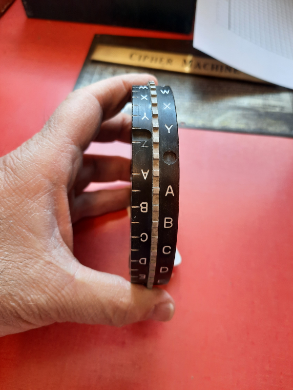
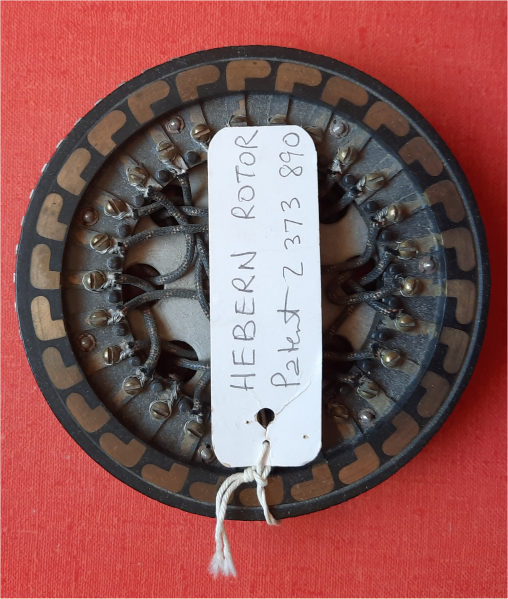
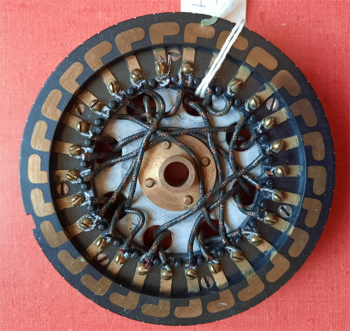
Among Hardie's documents, Moshe found a Hebern rotor. The photos he took are shown opposite [2].
Using an ohmmeter, Moshe noted the wiring. Then, he was able to deduce that this rotor corresponded to rotor number 3 of the 3-rotor machine described by D&K.
Here is the method Moshe used to find the wiring:
"I ‘am holding the rotor as follows :
- The U shaped indentation between Y and Z is on my left (letters upside-down).
- The O-shaped circle indentation is on my right.
In addition, Moshe noticed that the wiring of this rotor published by D&K is incorrect. The letter corresponding to X is a B and not a G.
Input Contact:  A B C D E F G H I J K L M N O P Q R S T U V W X Y Z
'' contact:     O L H C Y U R N J E A X T P K G D Z V Q M I F B W S  (rot. 3)
Additionally, Moshe told me that there were other errors in the wiring published by D&K:
- The first rotor has two K's and no G's.
- The second rotor has two Gs and no Fs.
- The output swap (printer) has two K's and no W's.
FootNotes:
- [1]: Moshe Rubin is a well-known cryptologist. He is a member of the ACA and is the worldwide Chaocipher cryptosystem specialist.
- [2]: If we look at the photo of the 3-rotor machine present at NCM, the rotor found by Moshe is different. Maybe it's from another Hebern machine? Hebern often reused the same wiring for different machines.
References
- Machine Cryptography and Modern Cryptanalysis,
by Cipher A. Deavours & Louis Kruh, Artech House Editor, 1985.
Note: this is the main source on the description of this 3-rotor machine.
Web links
-
National Cryptologic Museum. Browse the collection
(link).
Note: You can search by keyword. If we use the word "Hebern", we get several photos, including a 3-rotor Hebern machine from 1928 which prints and obviously inspired by the 5-rotor machine (2016-0704-0149). There are also photos of Hebern 3-rotor machines but a early model (simpler). - The Chaocipher" Clearing House.