Dismantling M-209
M-209 Workings Home Page
- M-209 Overview
-
Using
(Ciphering/Deciphering) - Inner setting
Disassembly by the operator
a. Operator Converter M-209-(*) can be sufficiently dismantled for the operator to make any minor repairs necessary by following the numbered step below:(1) Remove ink pad.
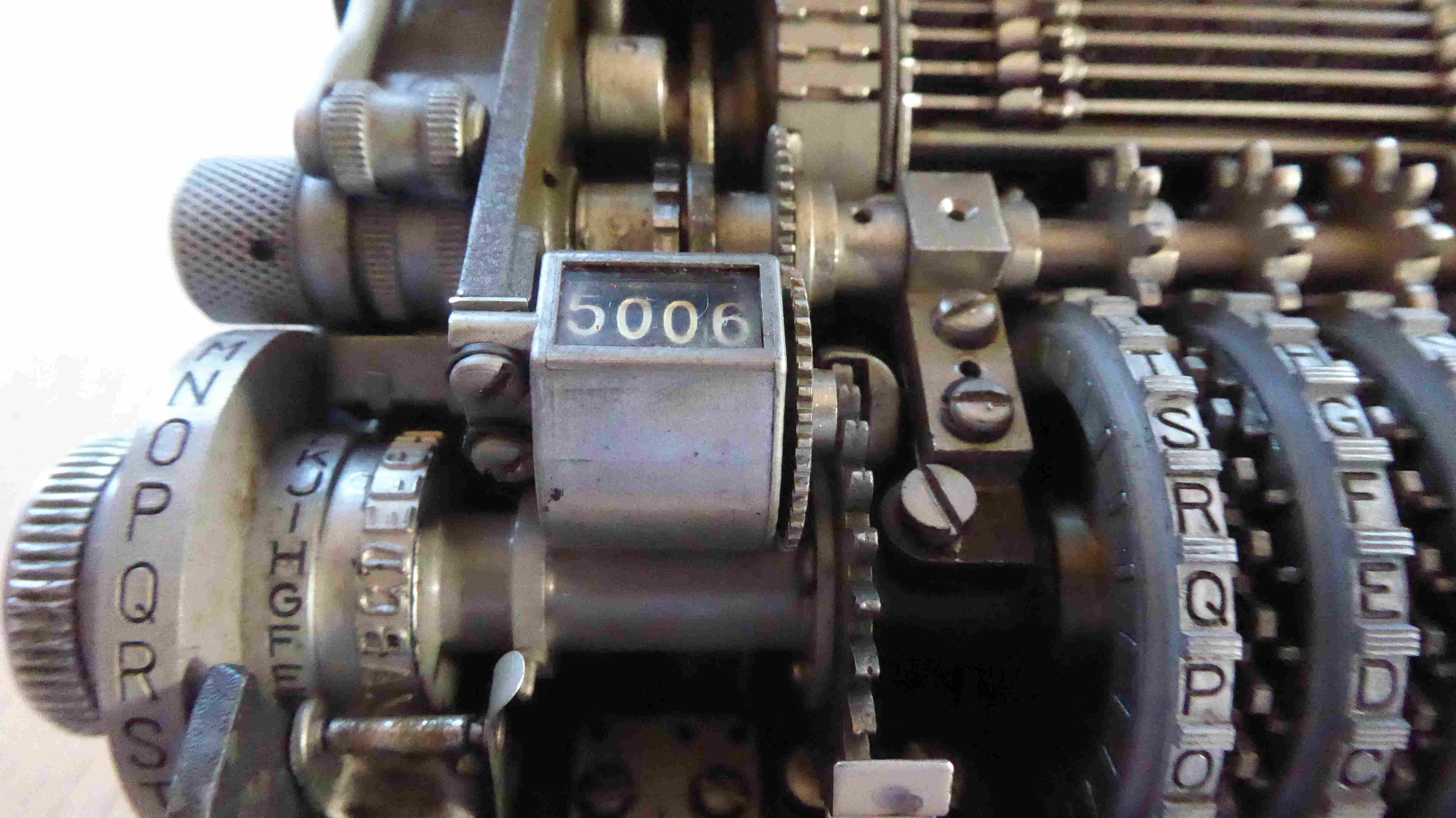
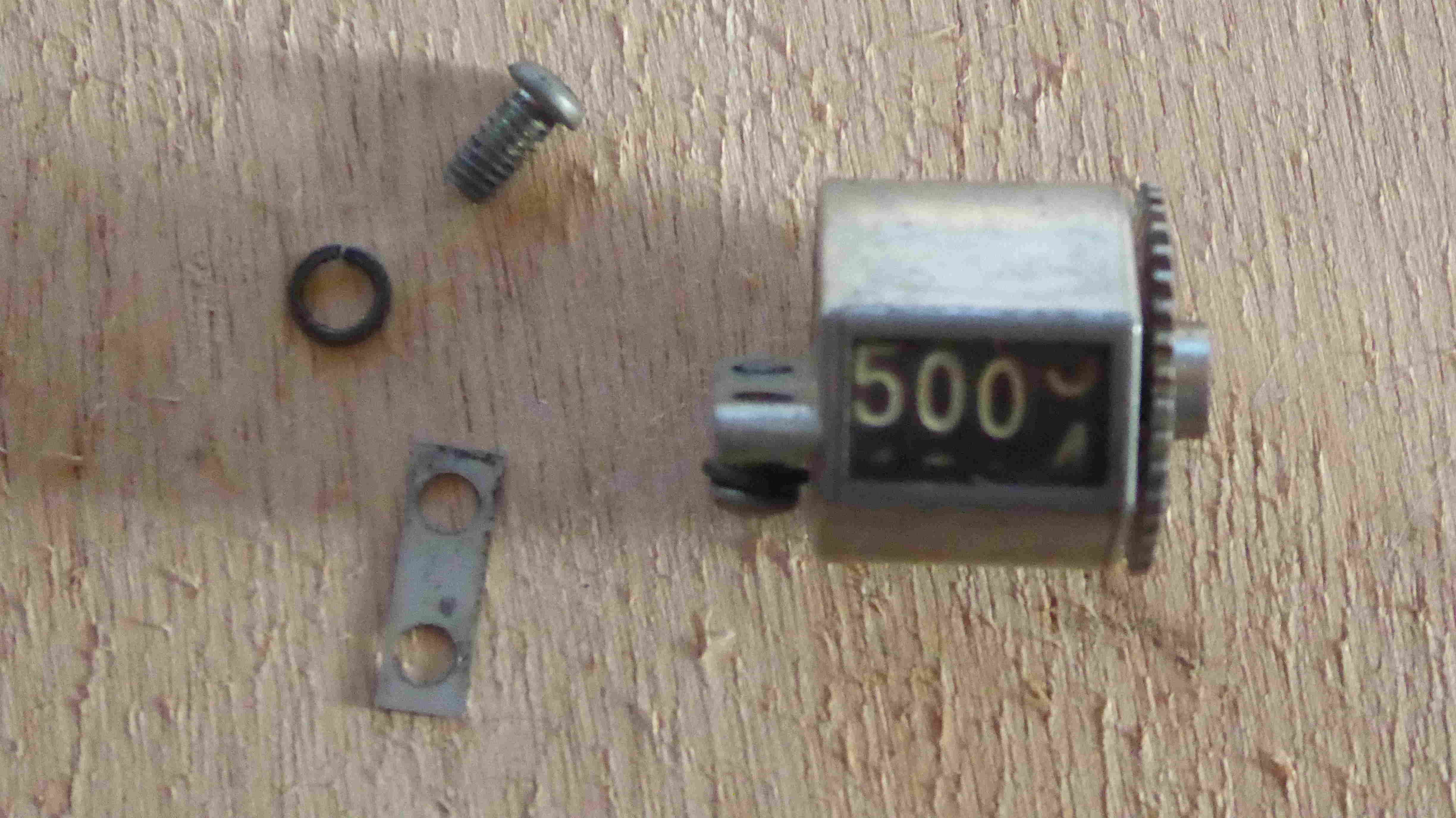
(2) Remove letter counter (two screws).
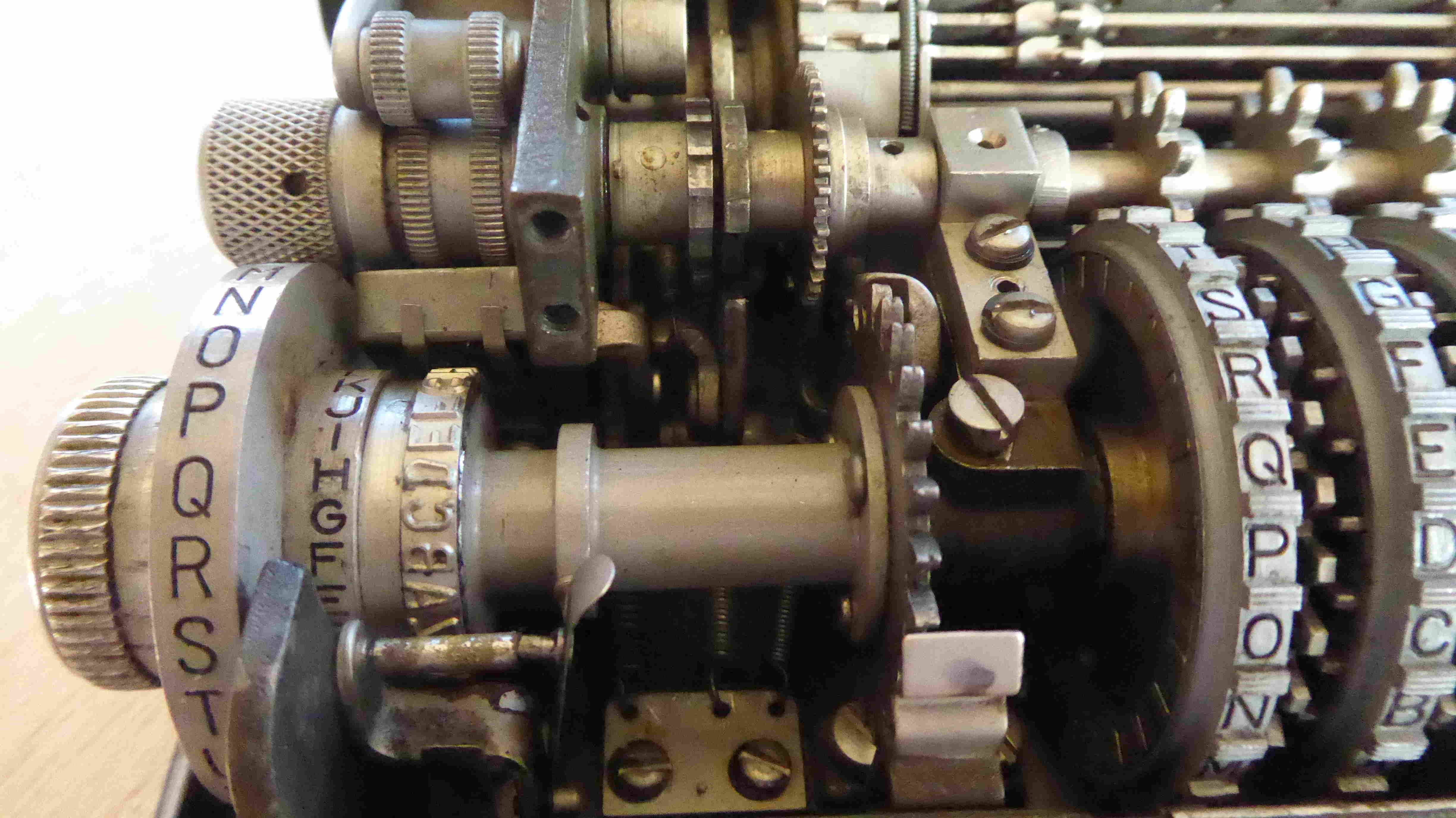
(3) Remove key weel left-end shaft screw.
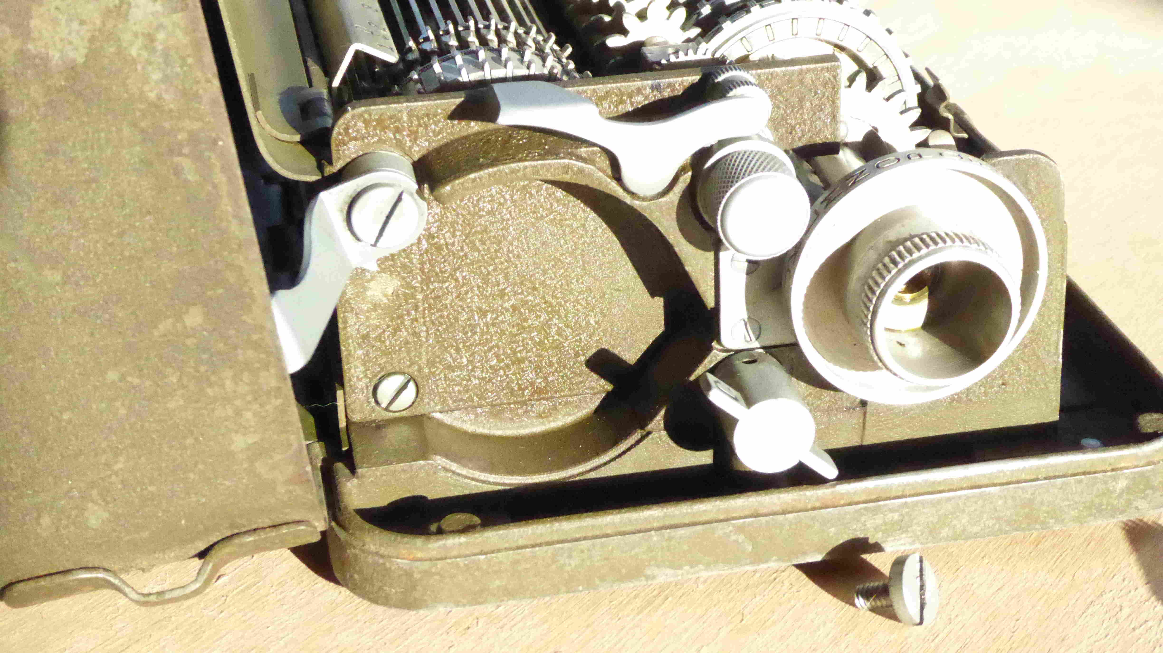
(4) Loosen key wheel bearing screw (fig. 9).
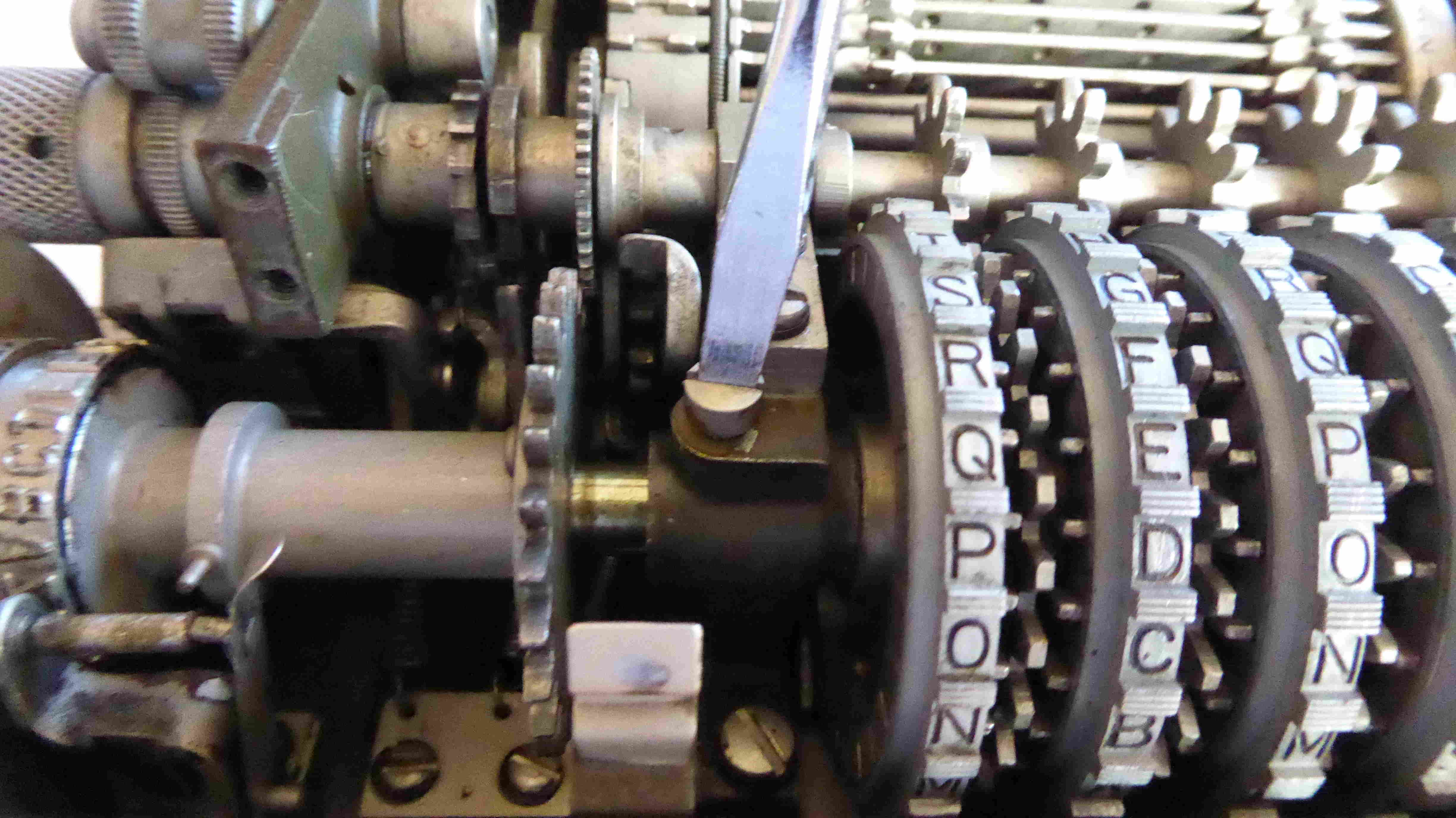
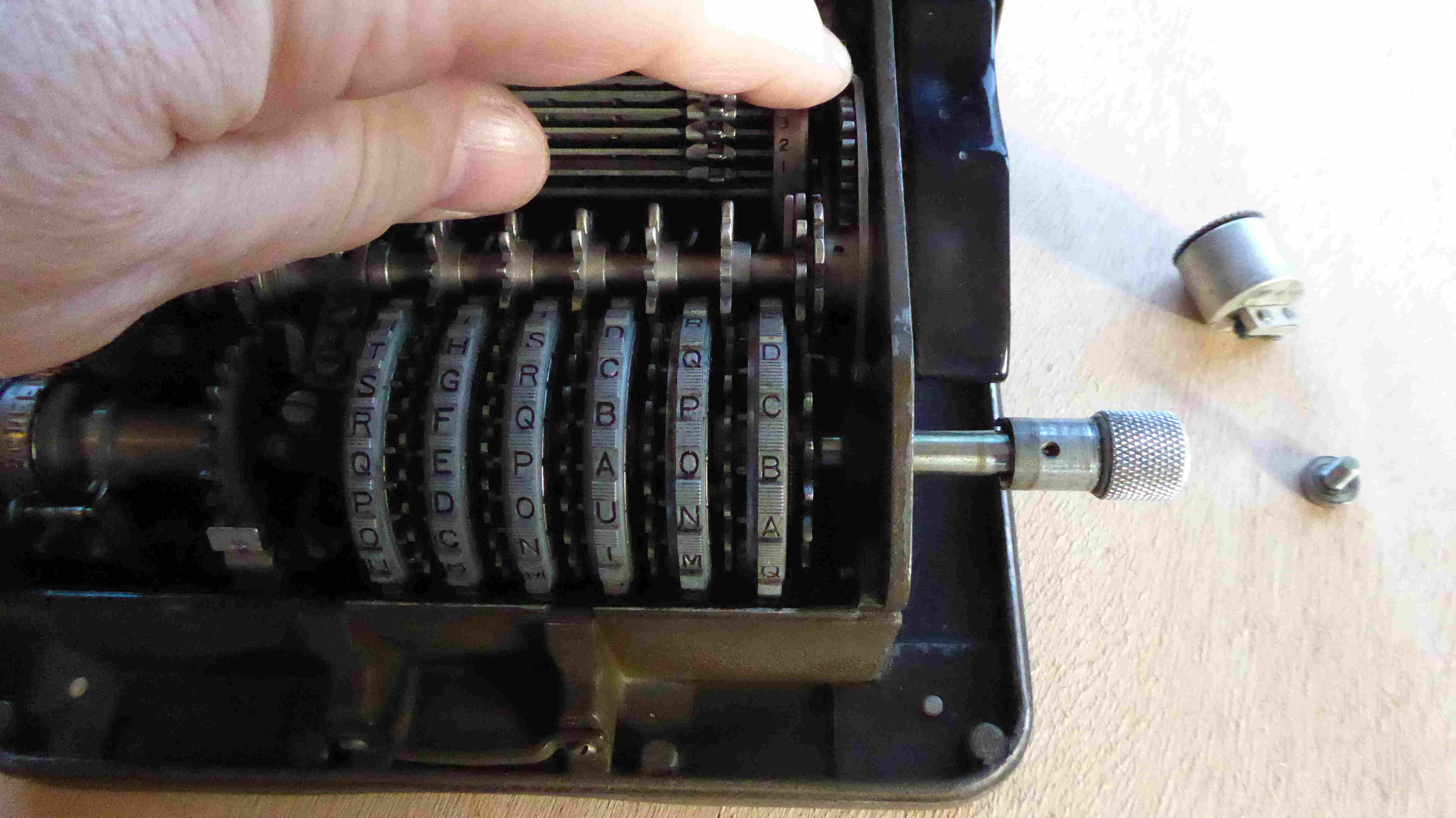
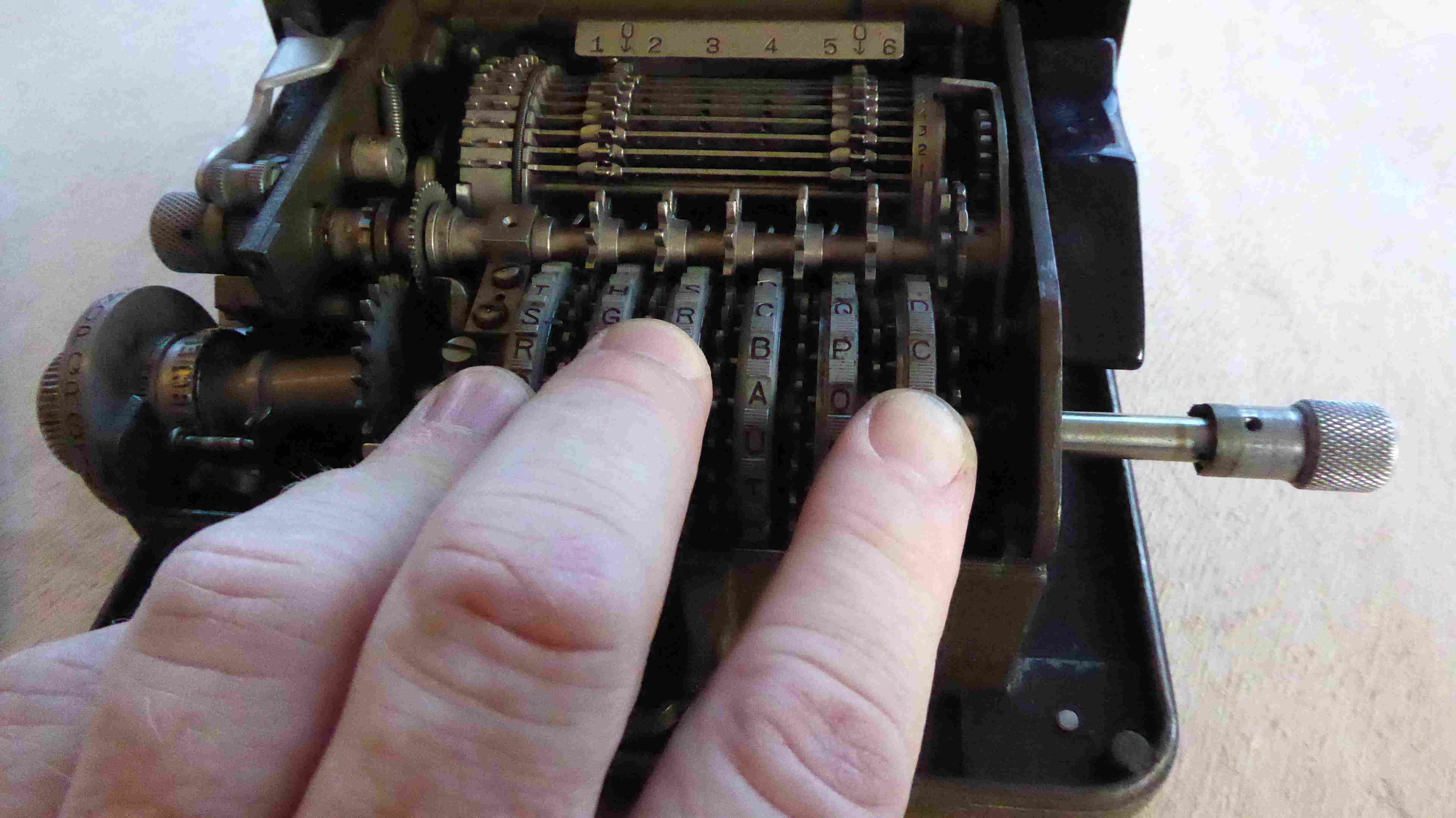
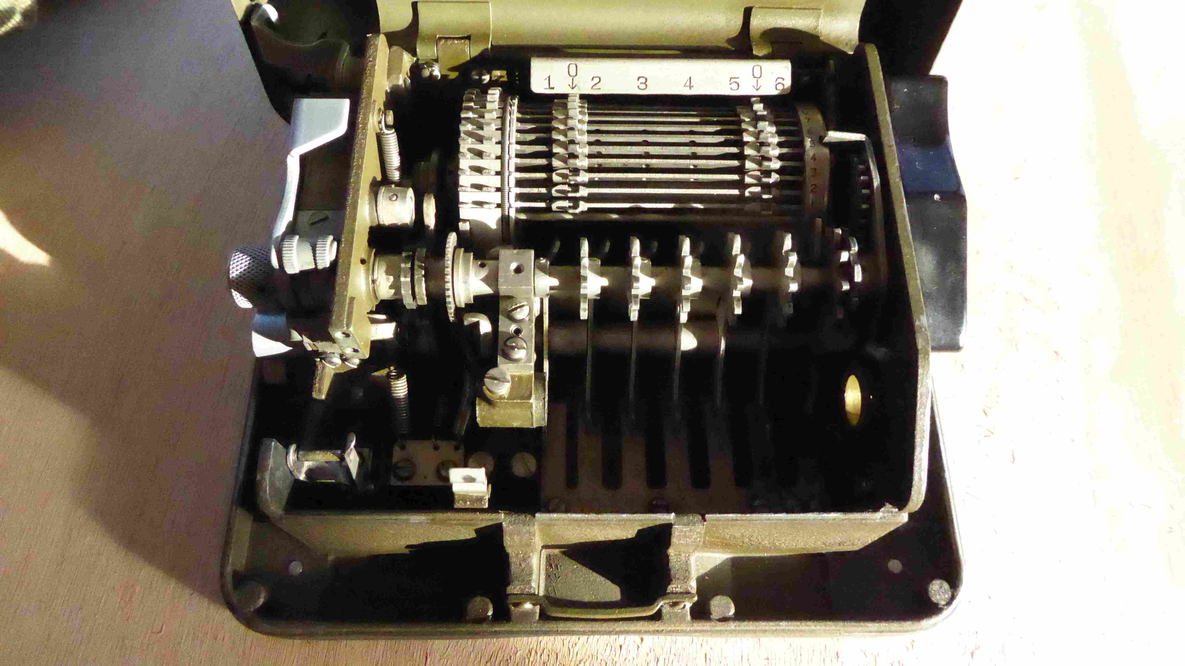
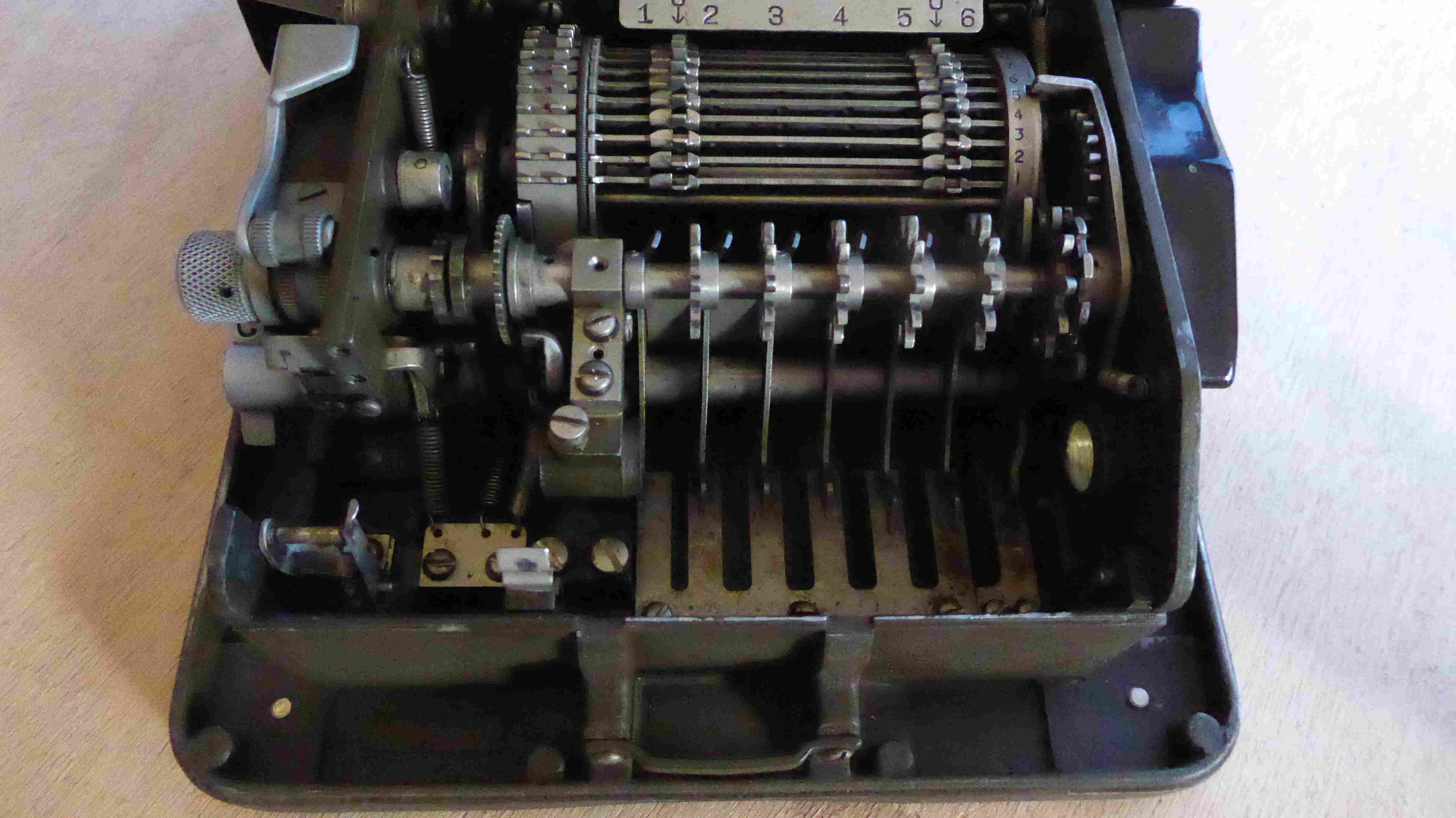
(5) Withdraw key wheel shaft (fig. 8) by pulling the reset knob (with the screw still in it) to the right, while rocking the key whells with the palm of the left hand.
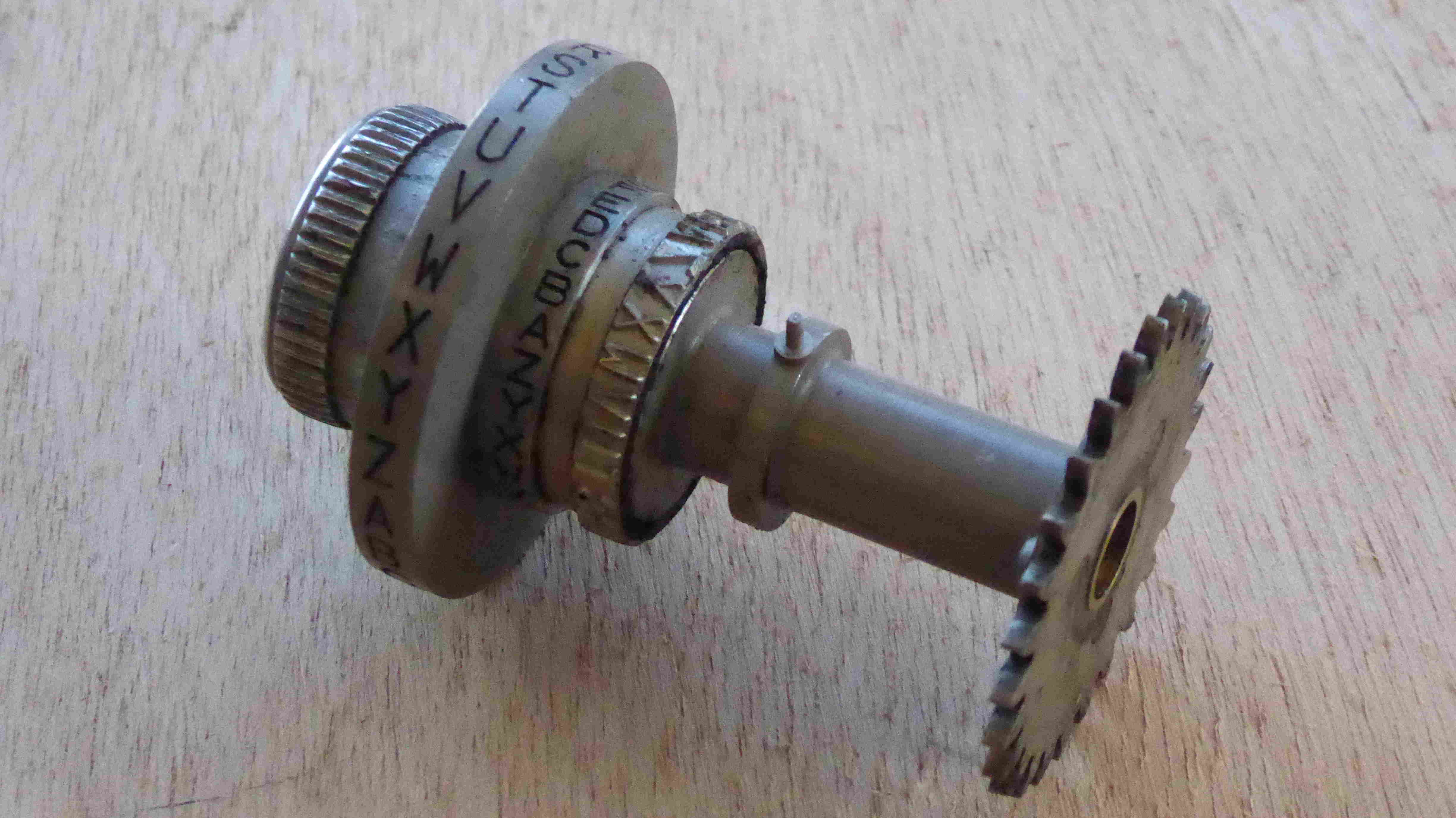
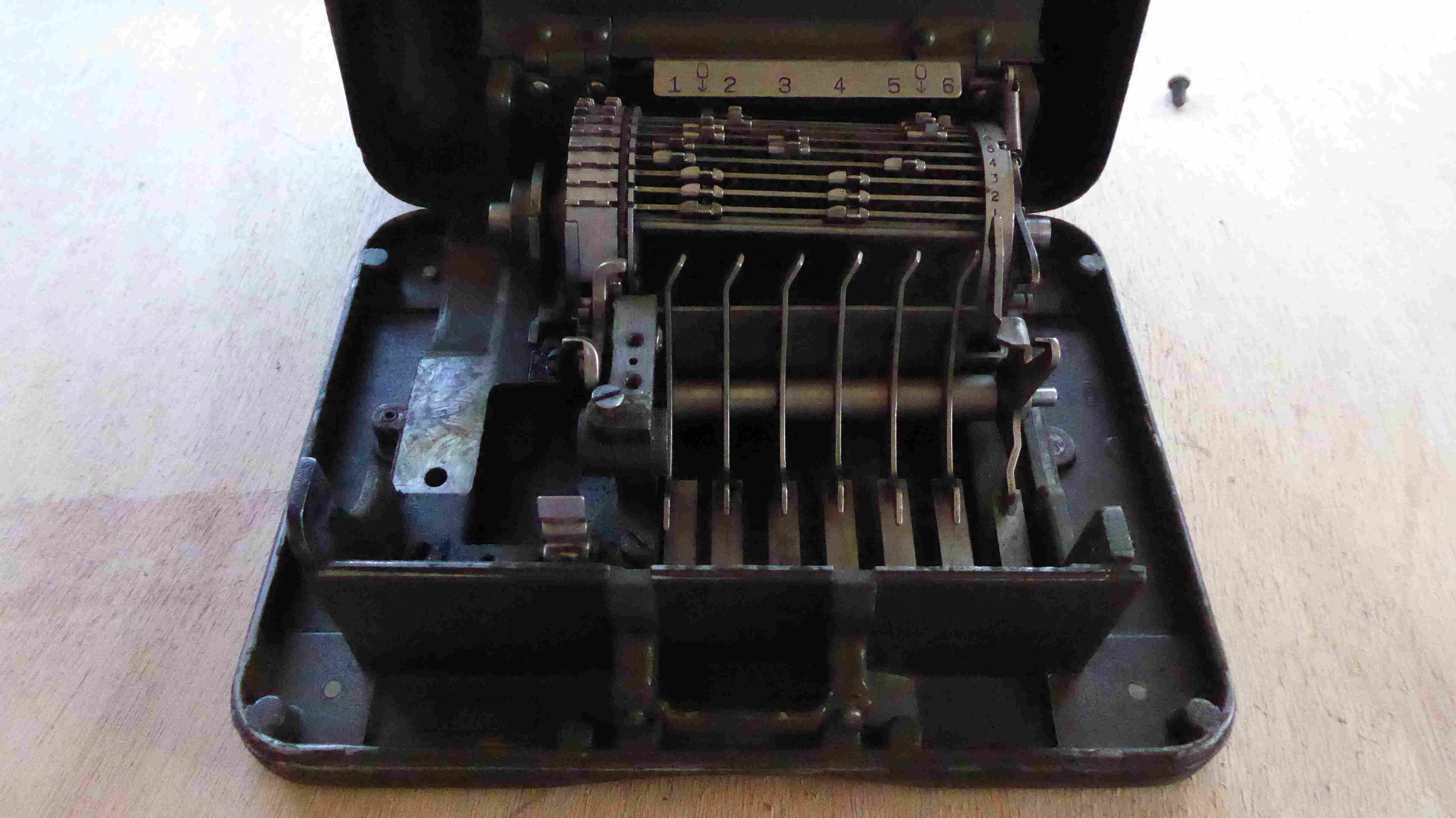
(6) Remove typewheel assembly (fig. 11). Pull the ink pad holder back when lifting the assembly out.
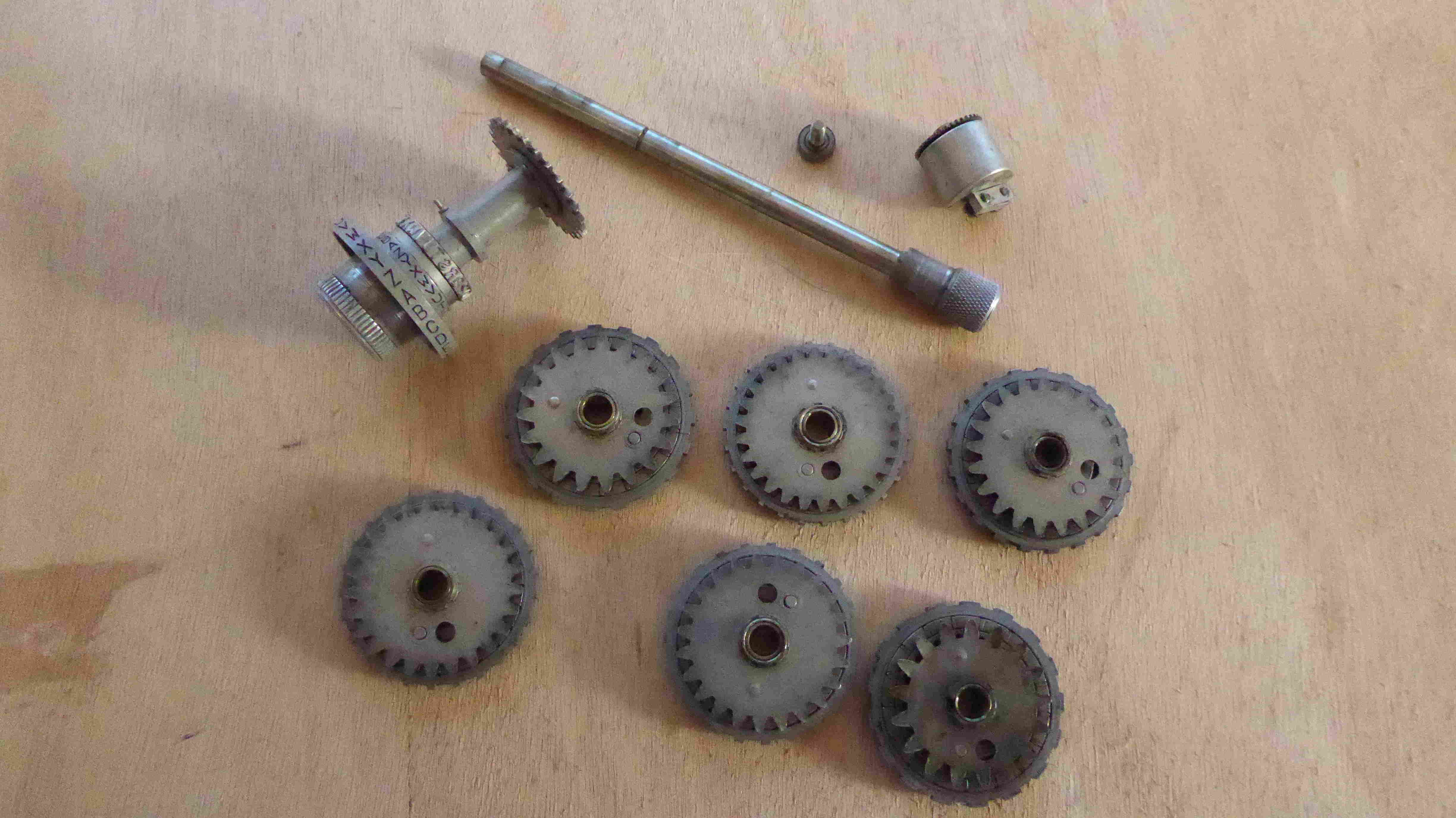
(7) Remove key wheels (fig. 8).
|
|
|
| Before dismantling | The letter counter | After dismantling the letter counter |
|
|
|
| Before dismantling | key wheel left-end shaft screw | Loosen key wheel bearing screw |
|
|
|
| Withdraw key wheel shaft ... | while rocking the key wheels with the palm ... | key wheels and typewheel |
|
|
|
| The Typewheel | After dismantling | After dismantling |
Disassembly by the Repairman
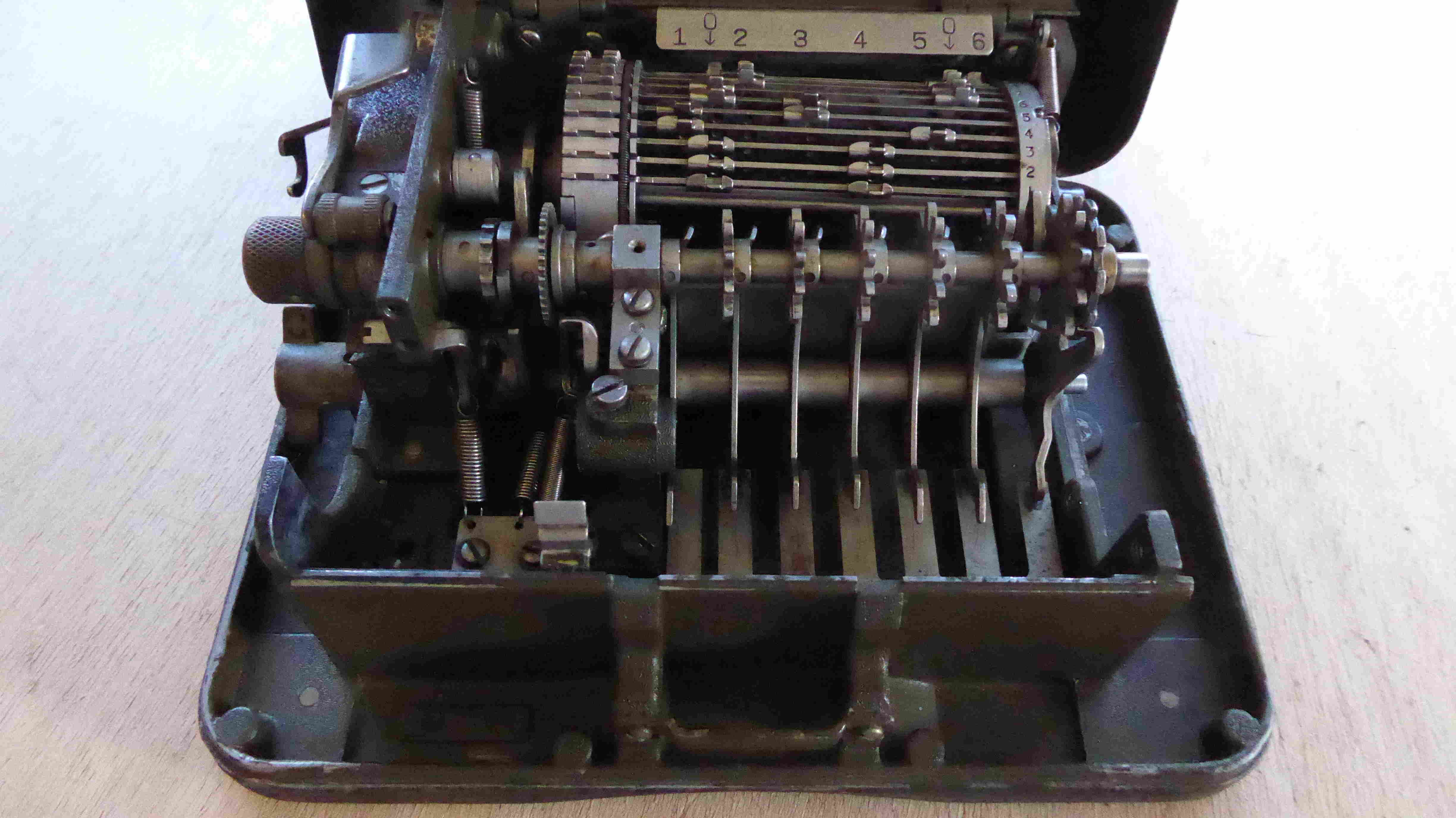
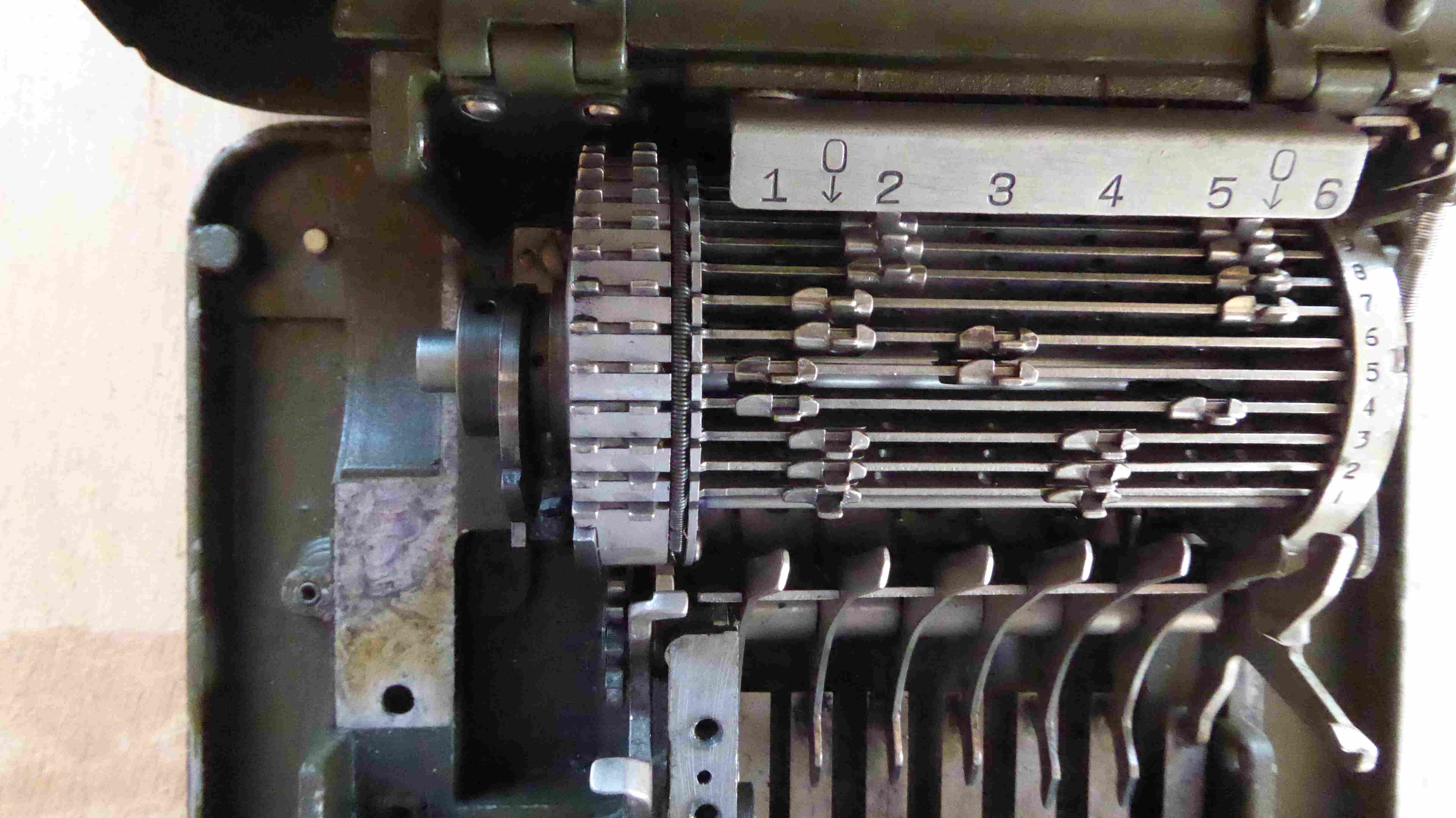
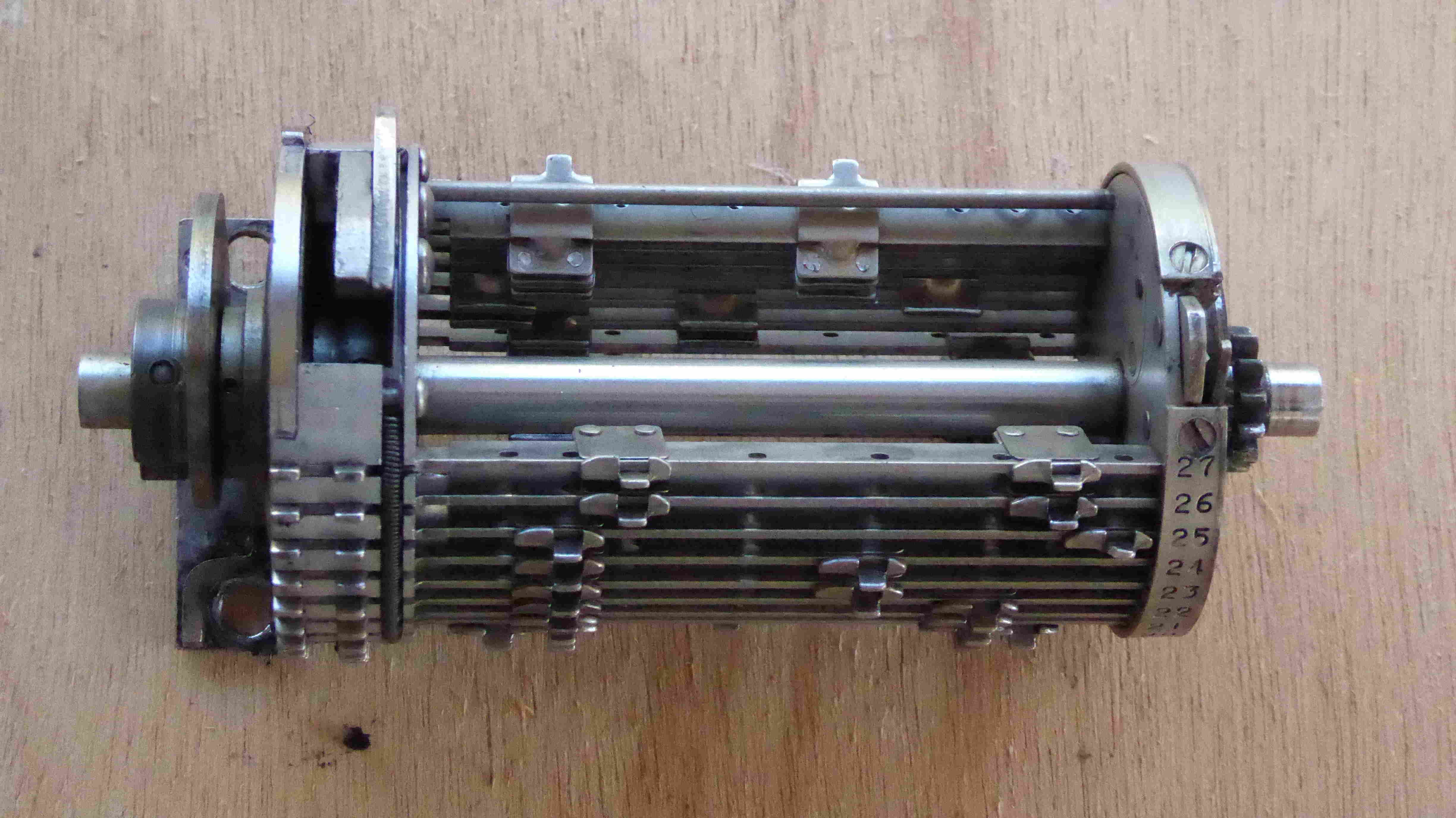
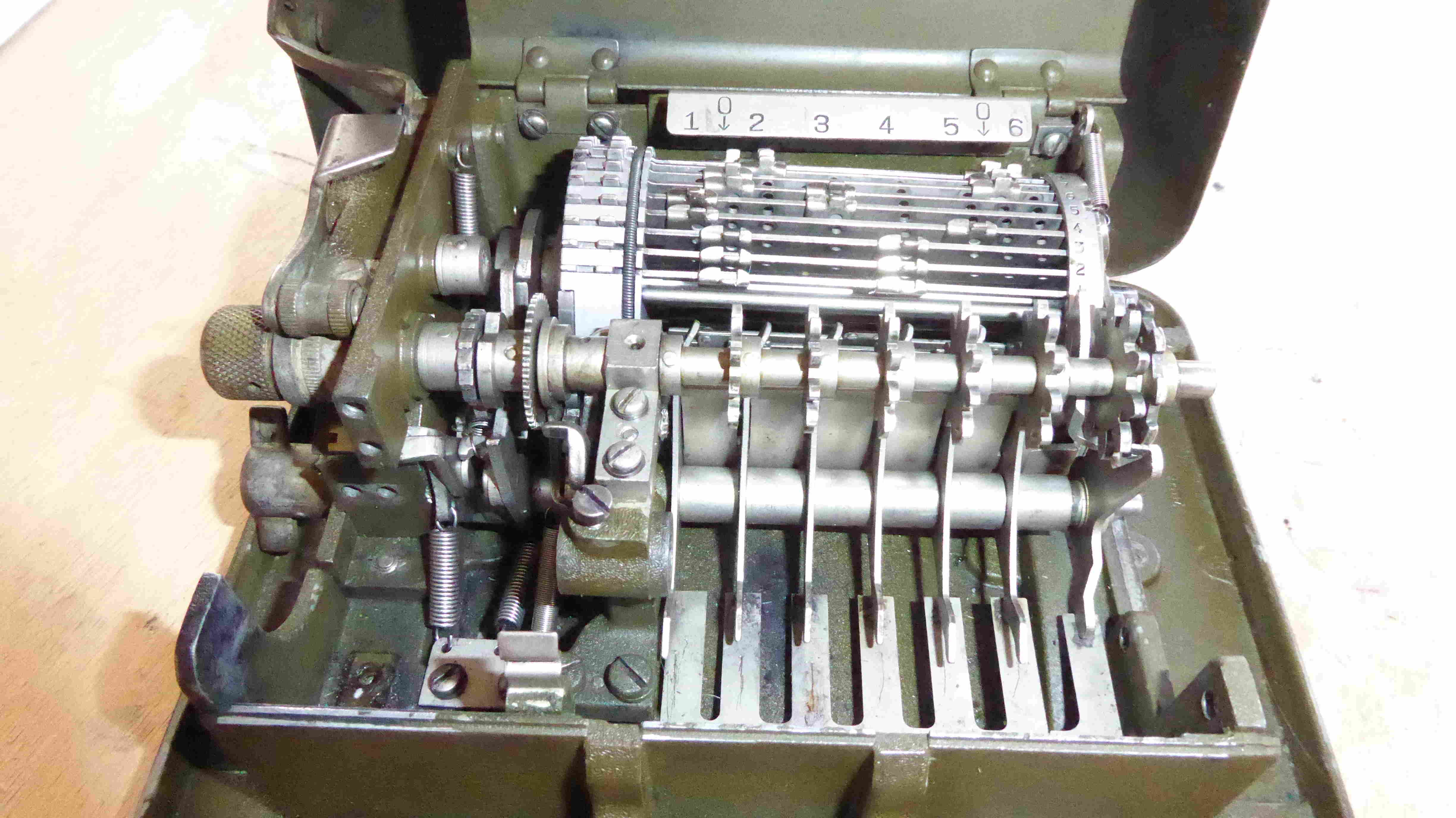
b. Repairman If a converter requires more than minor repair it must be serviced by a repairman. In addition to the dismantling procedure authorized an operator, a repairman will continue dismantling as follow:(1) Revolve the drum in the usal maner until 27 on the number disk is the only number visible; then remove the drum bar lug number plate (fig. 3, (29)) by taking out the two screws, lockwashers, and spacing washer. (After removing number plate, complete the drum cycle.)
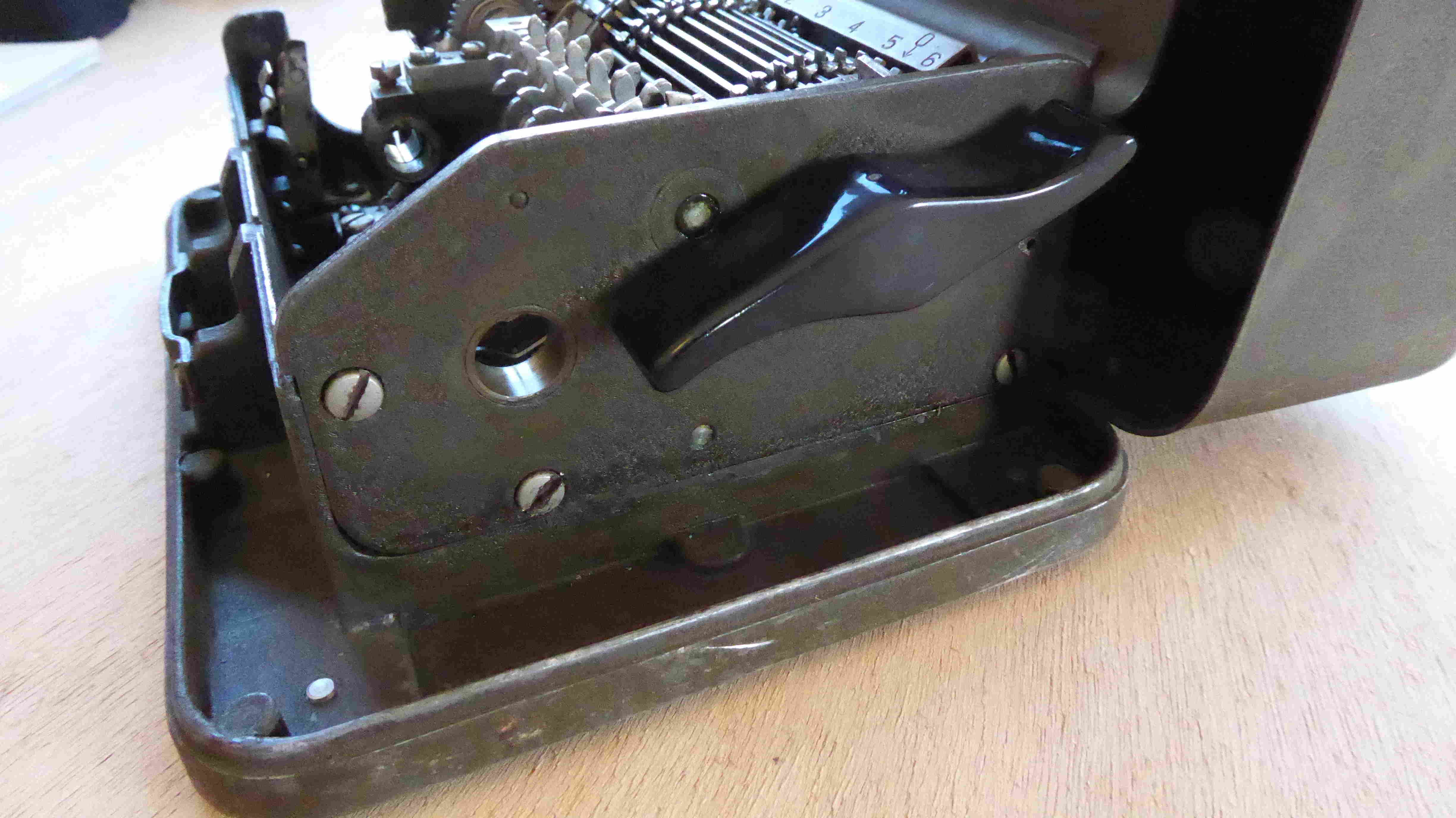
(2) Remove the right side-plate (4 screws). Note the dowel wich is fitted into the end of the rear plate of the machine. The side-plate must be pulled straight out in order to prevent bending the dowel.
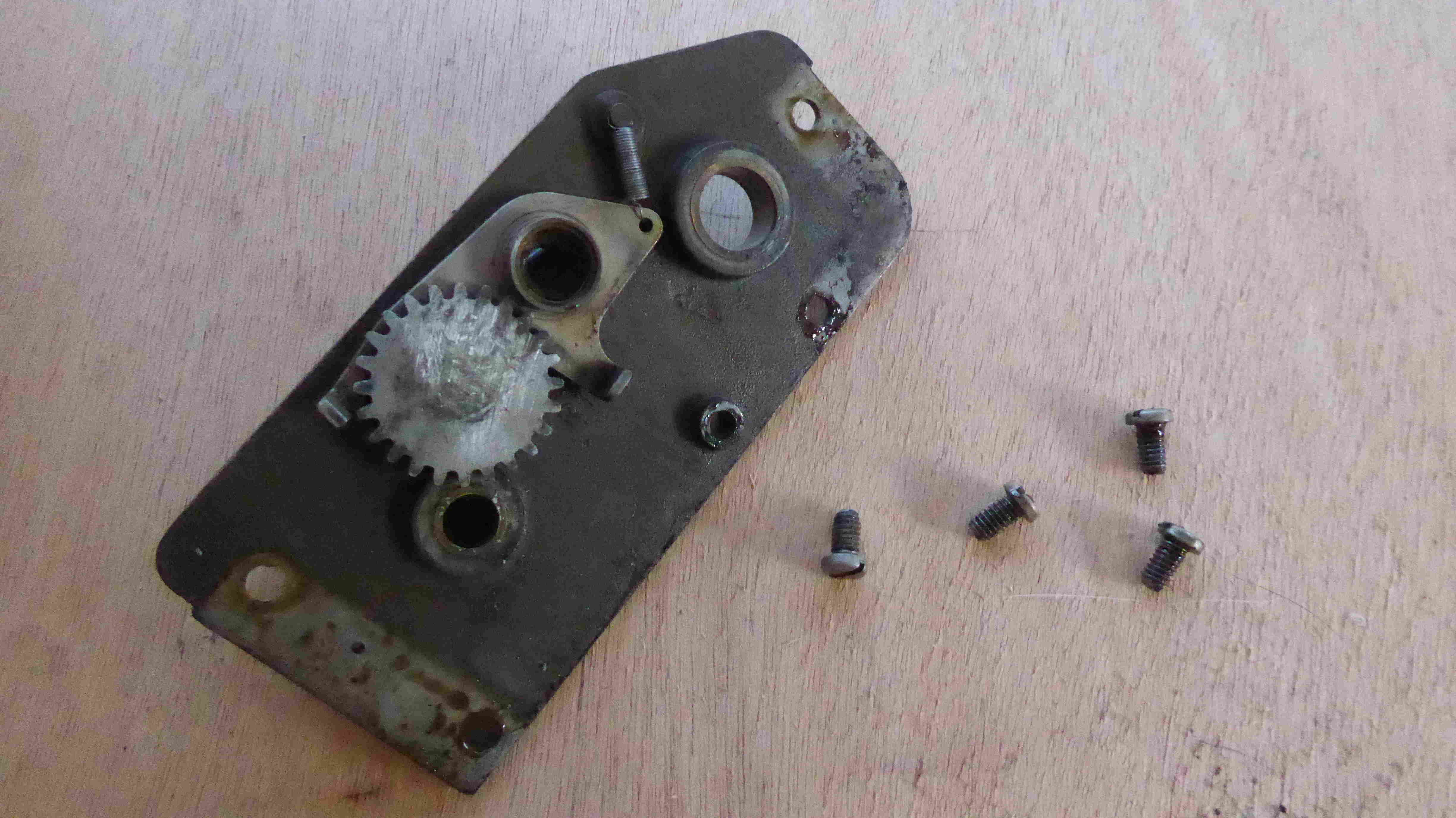
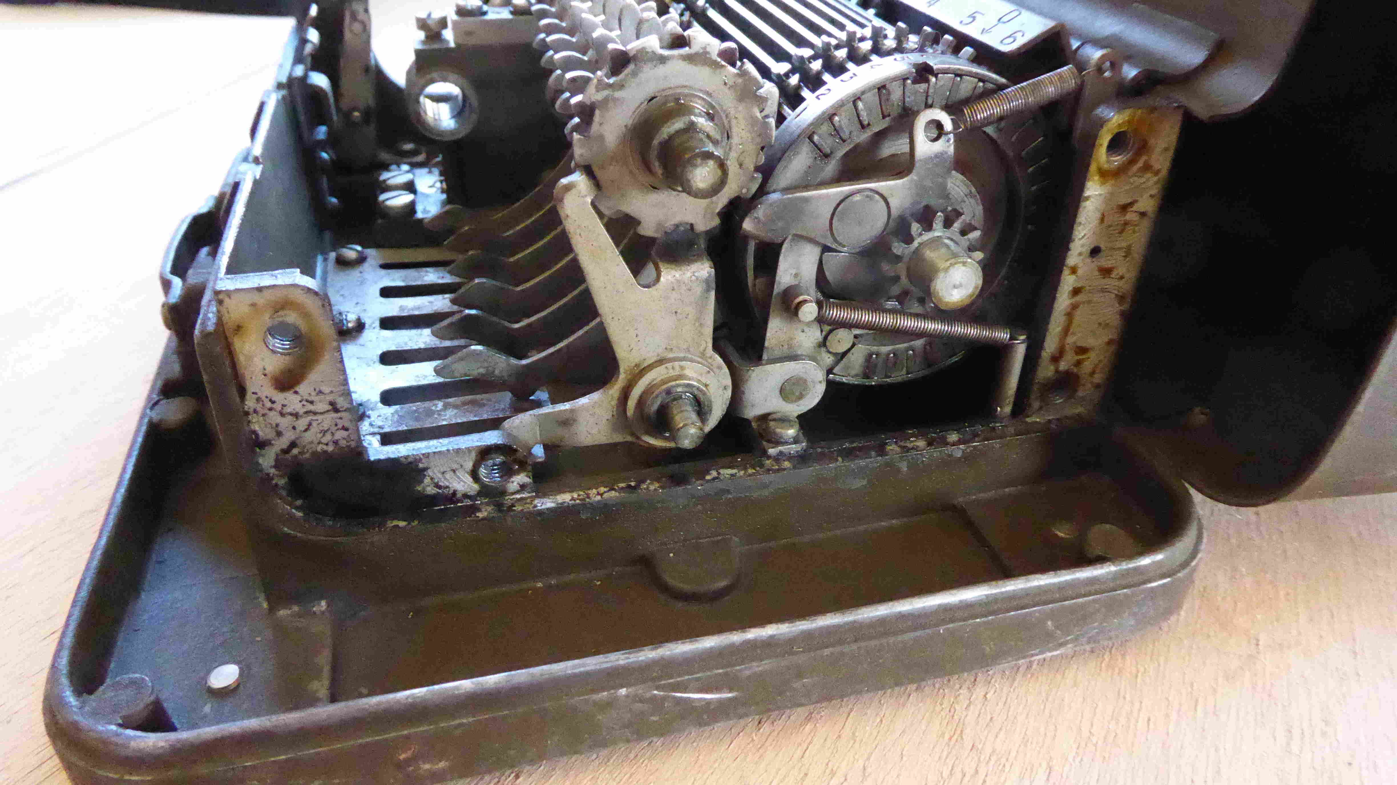
(3) Remove the intermidate gear assembly (2 screws). Do not bend the dowel between the two screws (fig. 8).
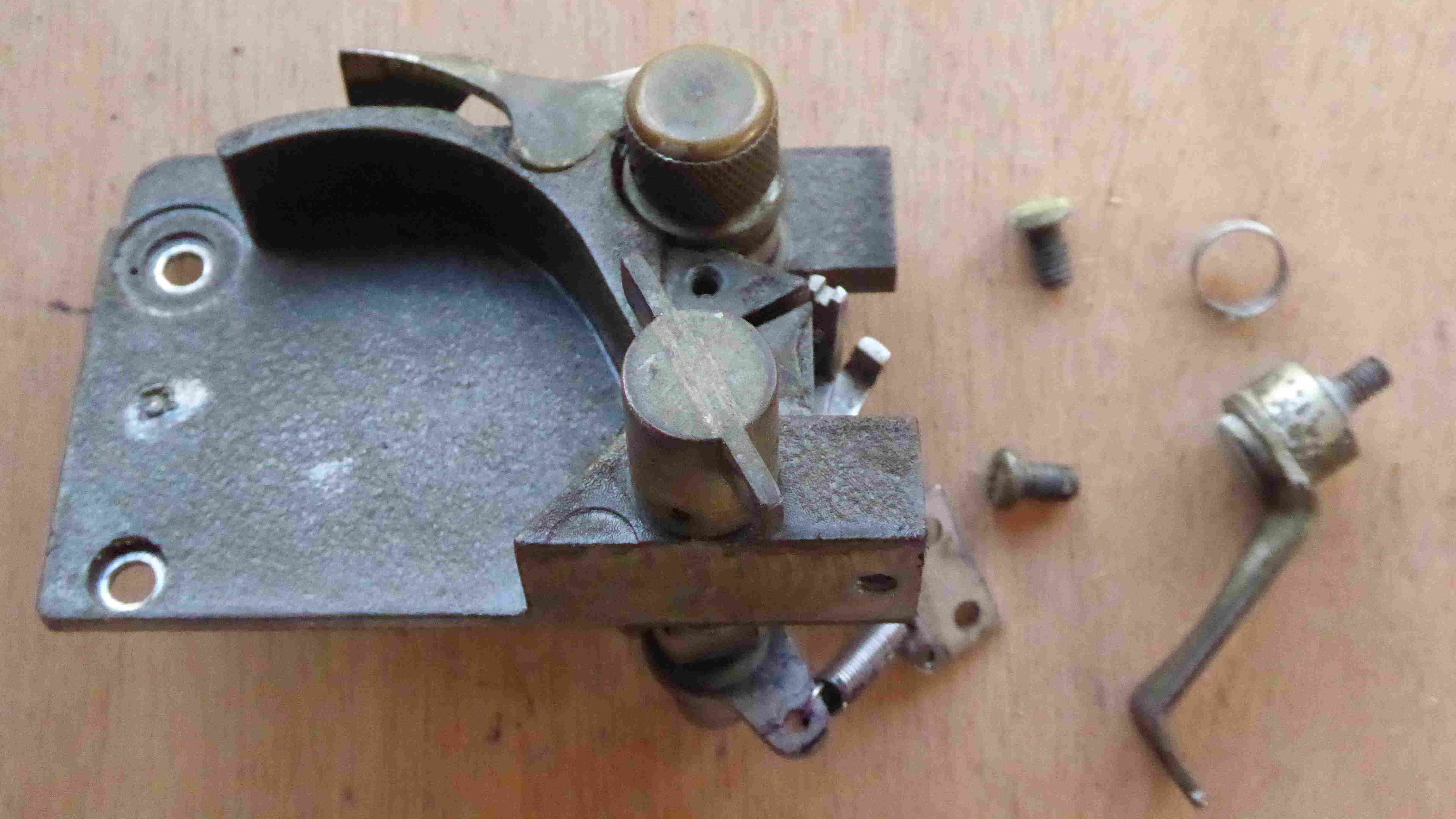
(4) Remove the left side-plate, proceeding as follows:
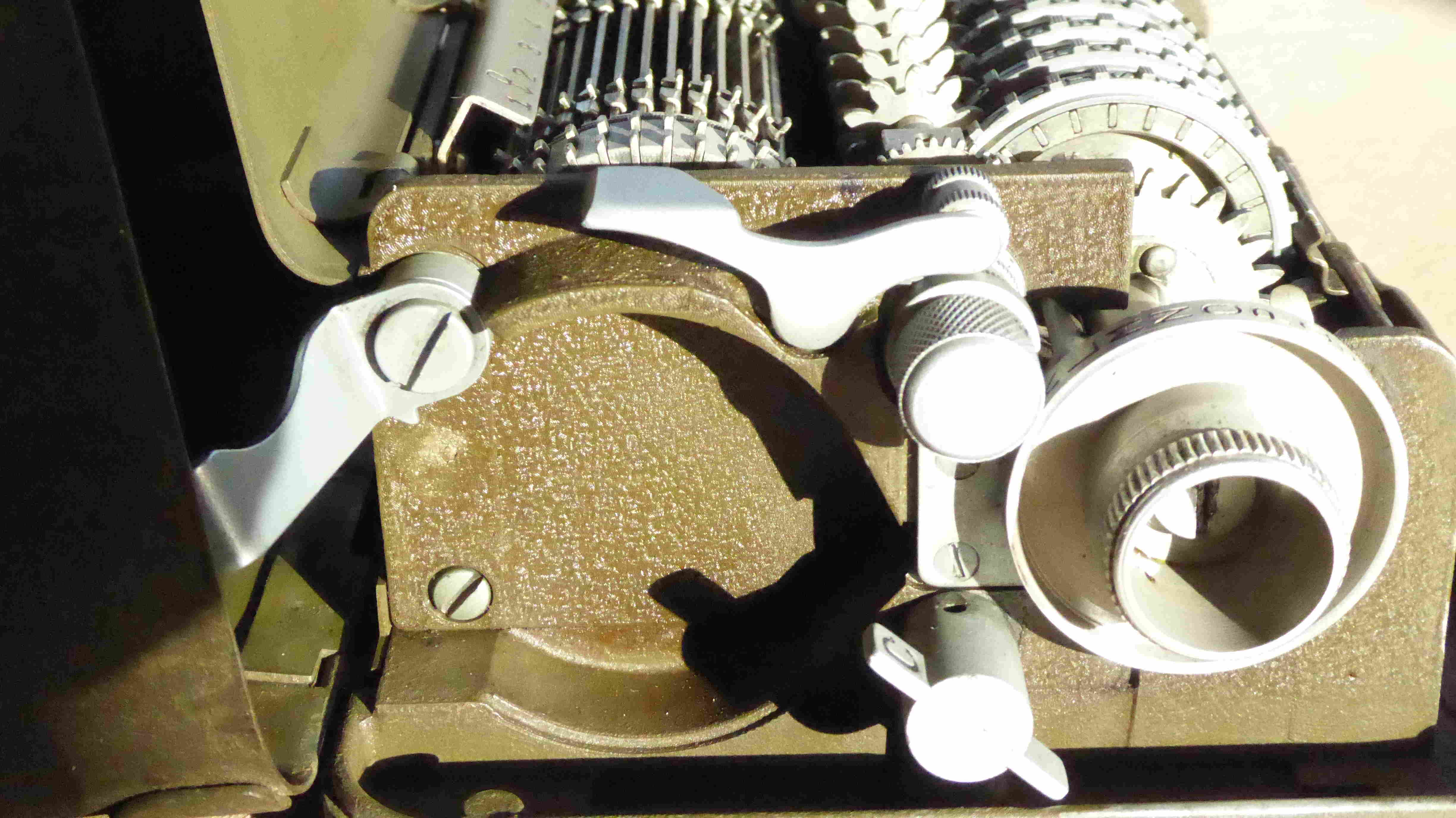
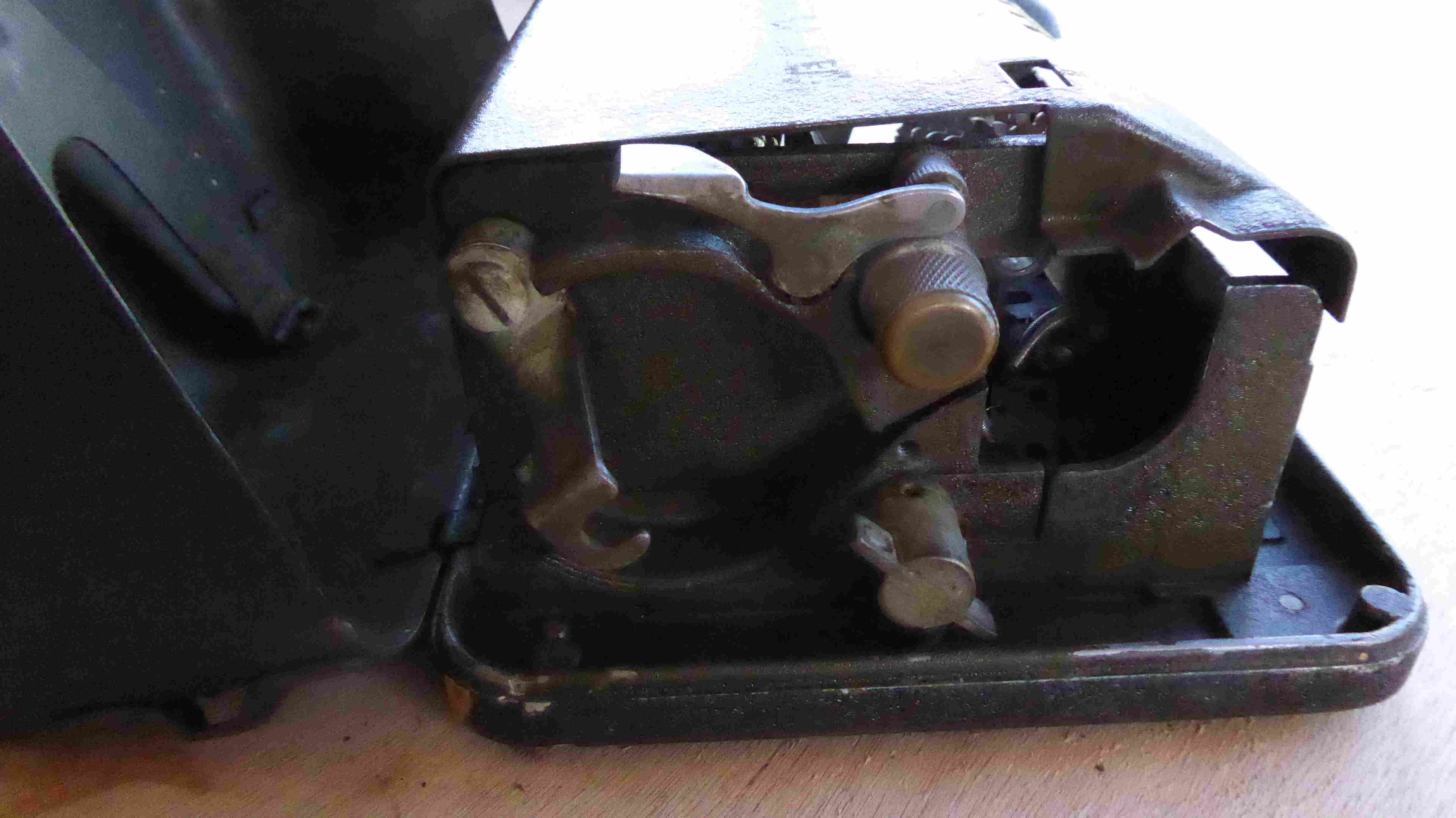
- (a) Unhook the print arm spring and the paper feed arm spring from the spring clip (fig. 12).
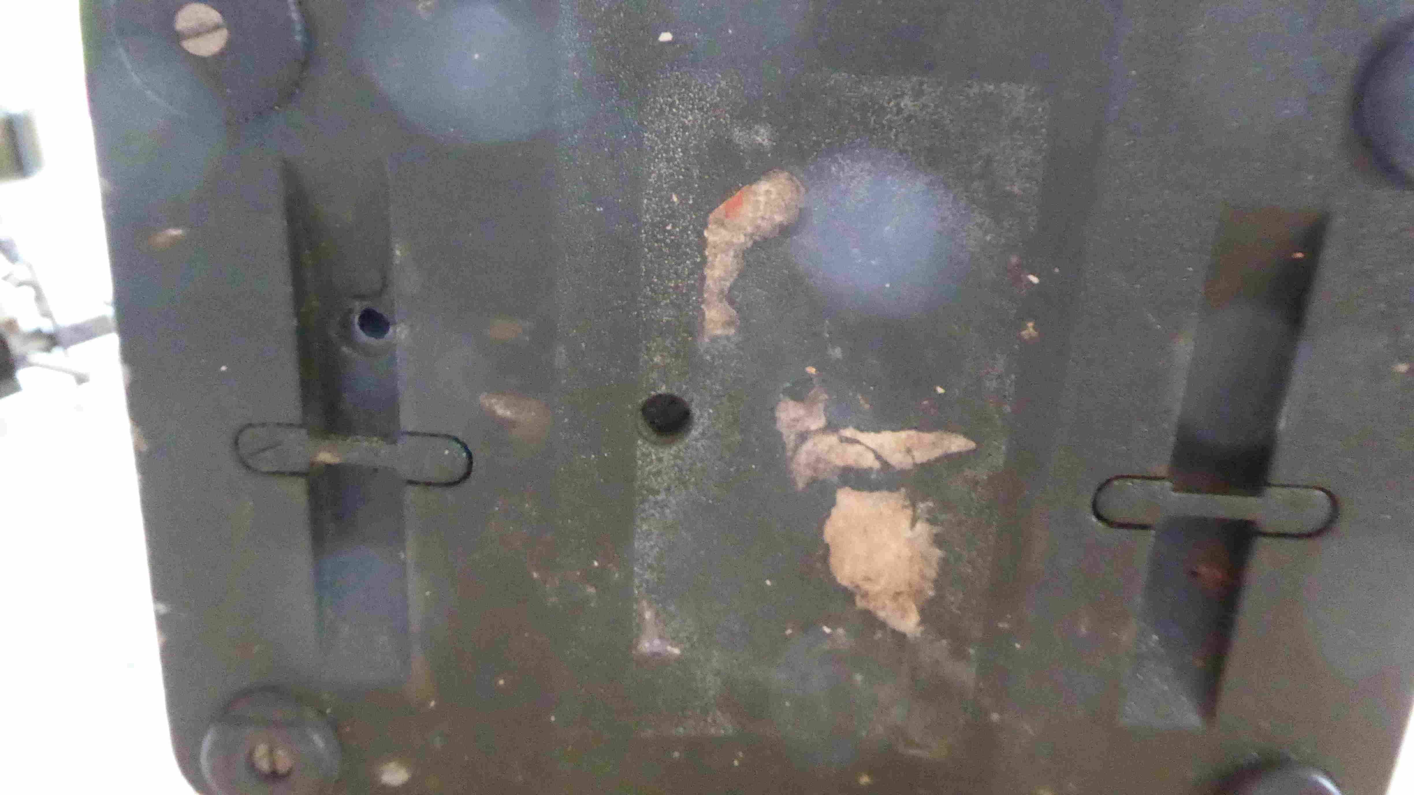
- (b) Remove the screw on the left of the underside of the base. This screw holds the encipher-decipher knob detent ball and spring in place. Remove the ball and spring.
- (c) Remove the screw in the inset on the underside of the base.
- (d) Remove the screw on the lower back of the left side-plate.
- (e) Remove the screw spwing and latch assembly on the upper back of the left side-plate.
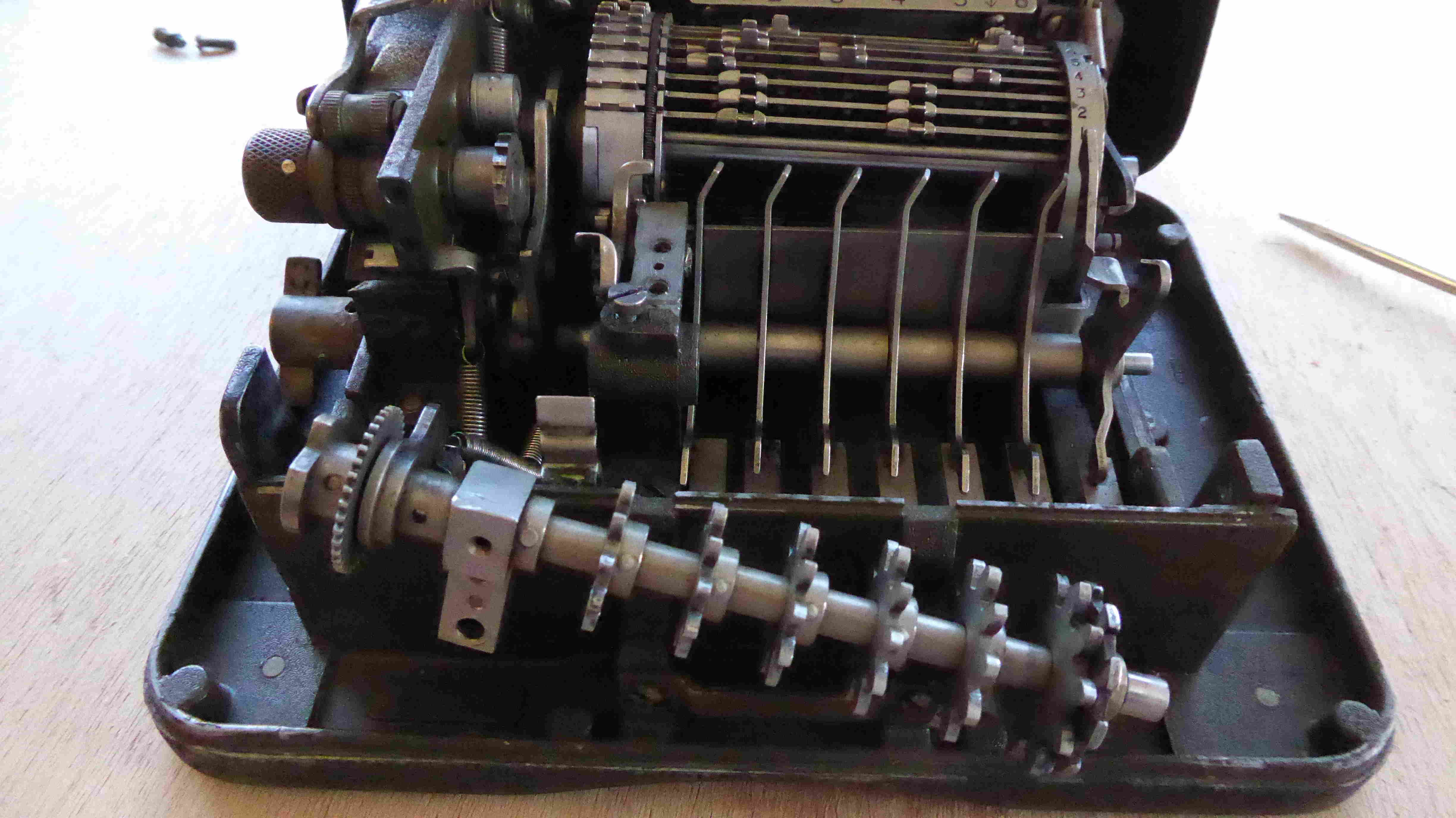
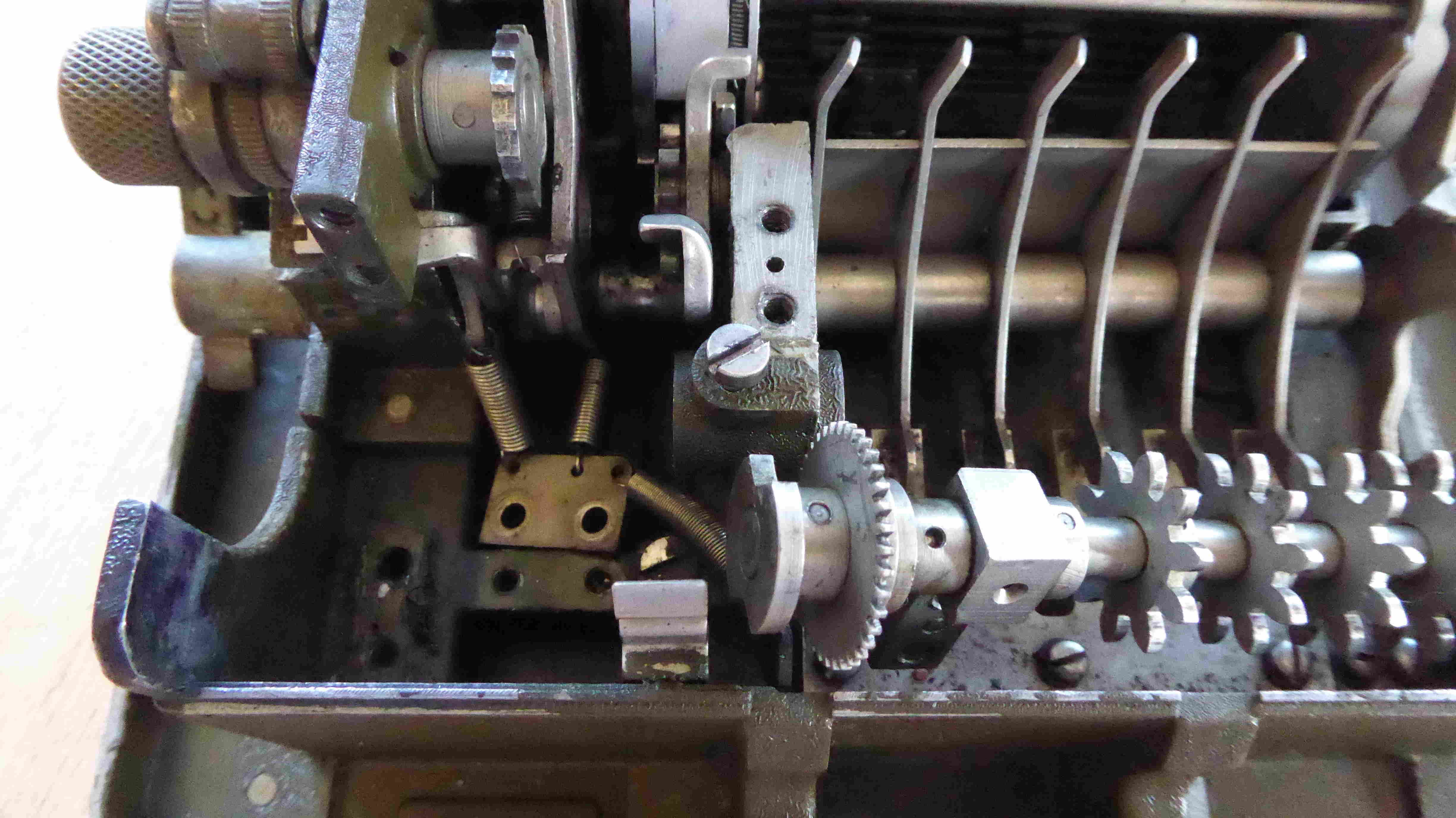
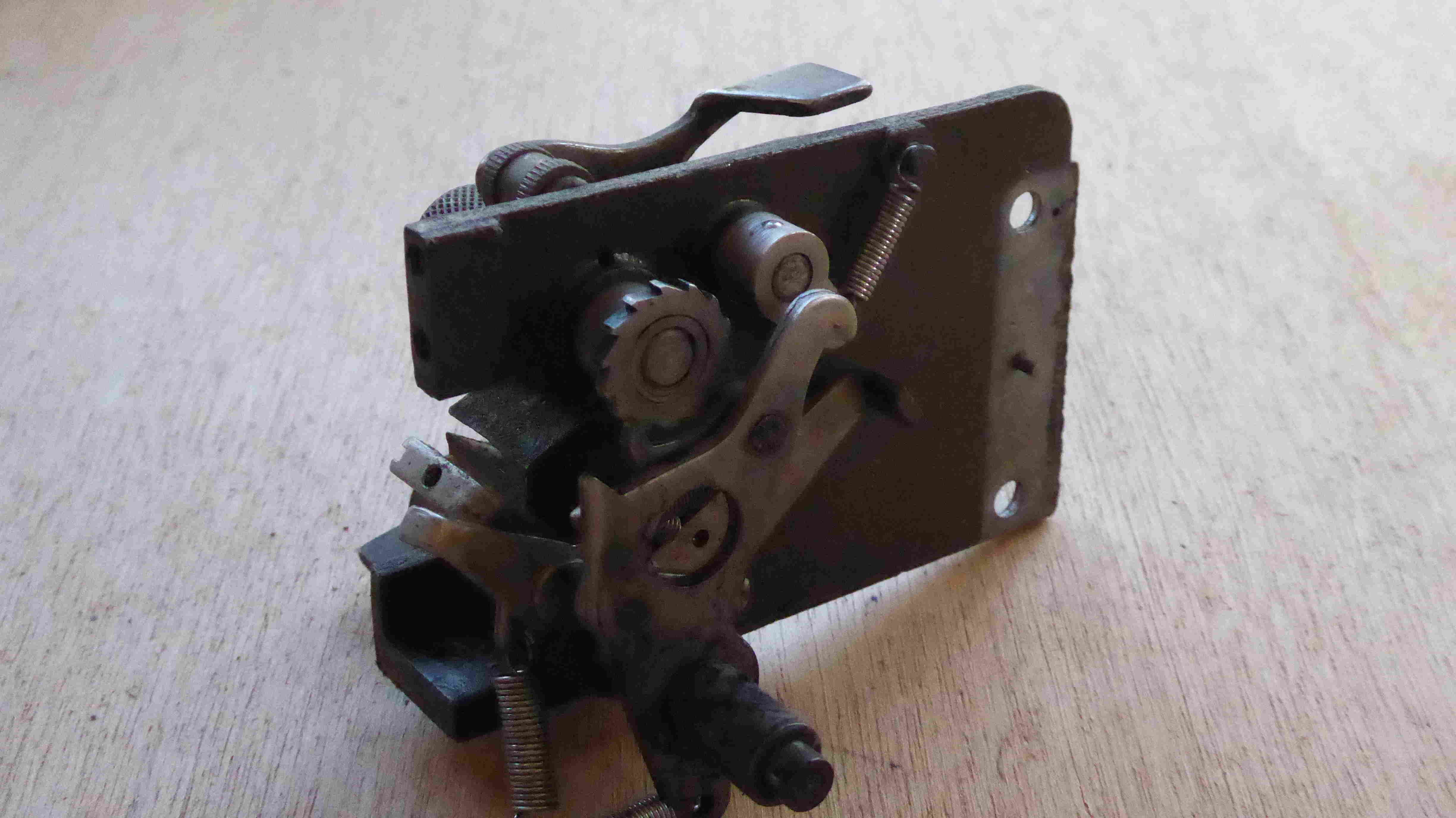
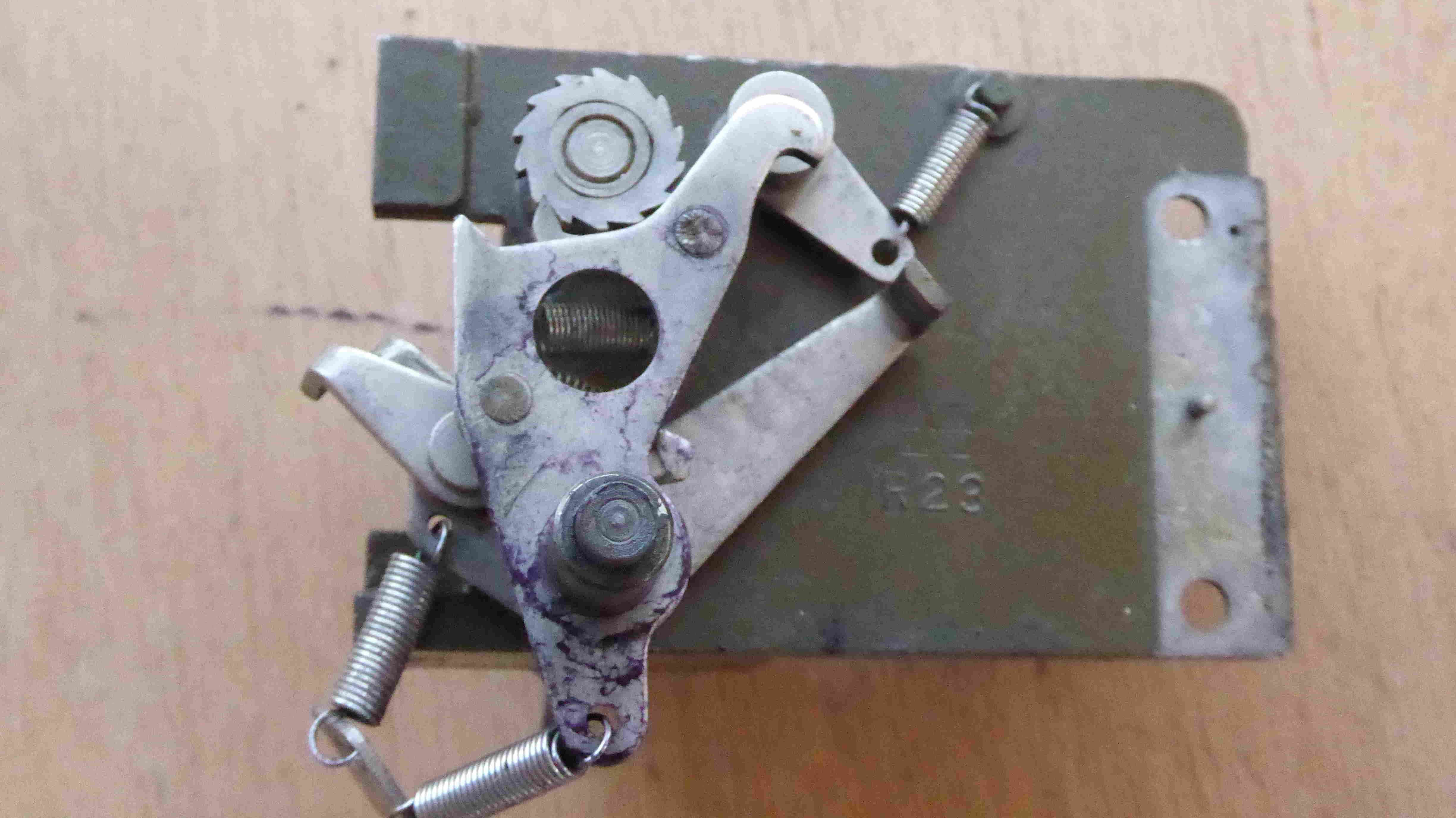
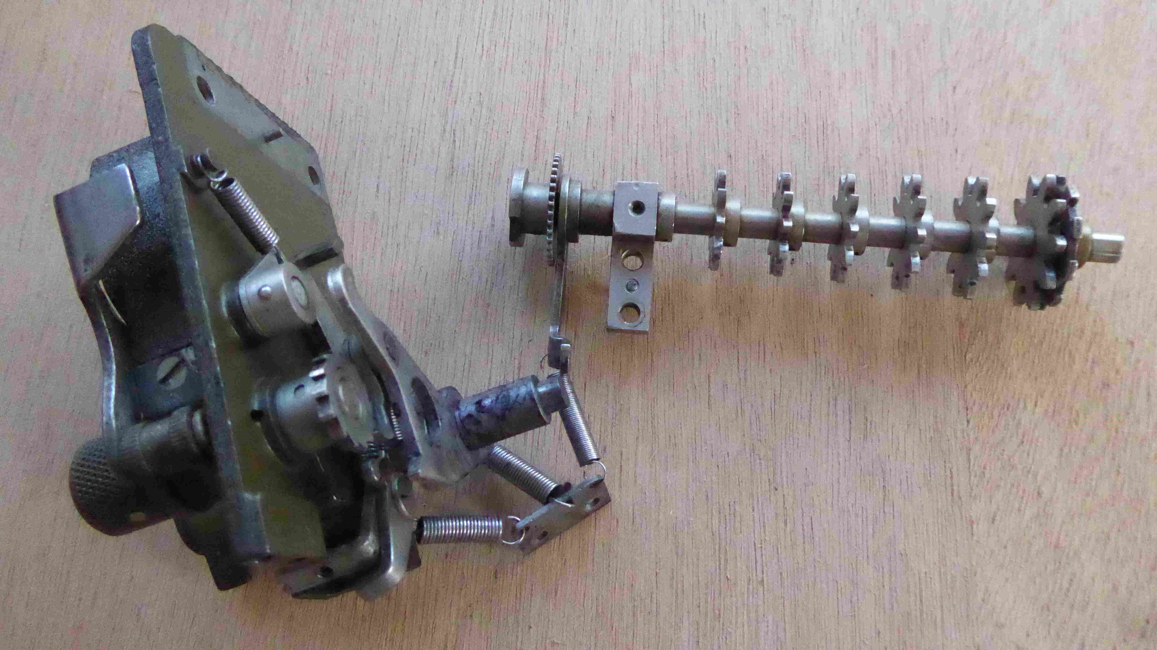
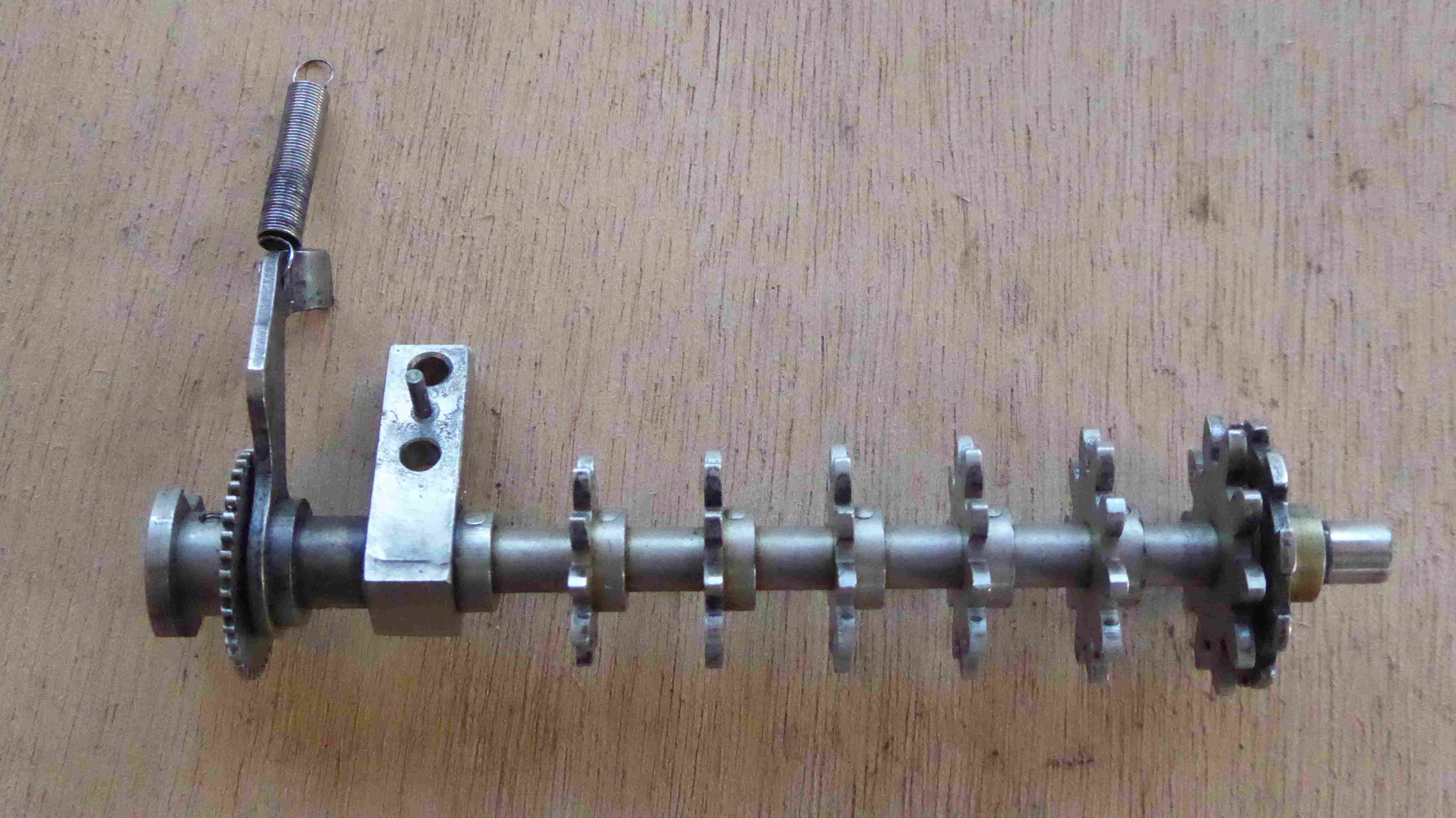
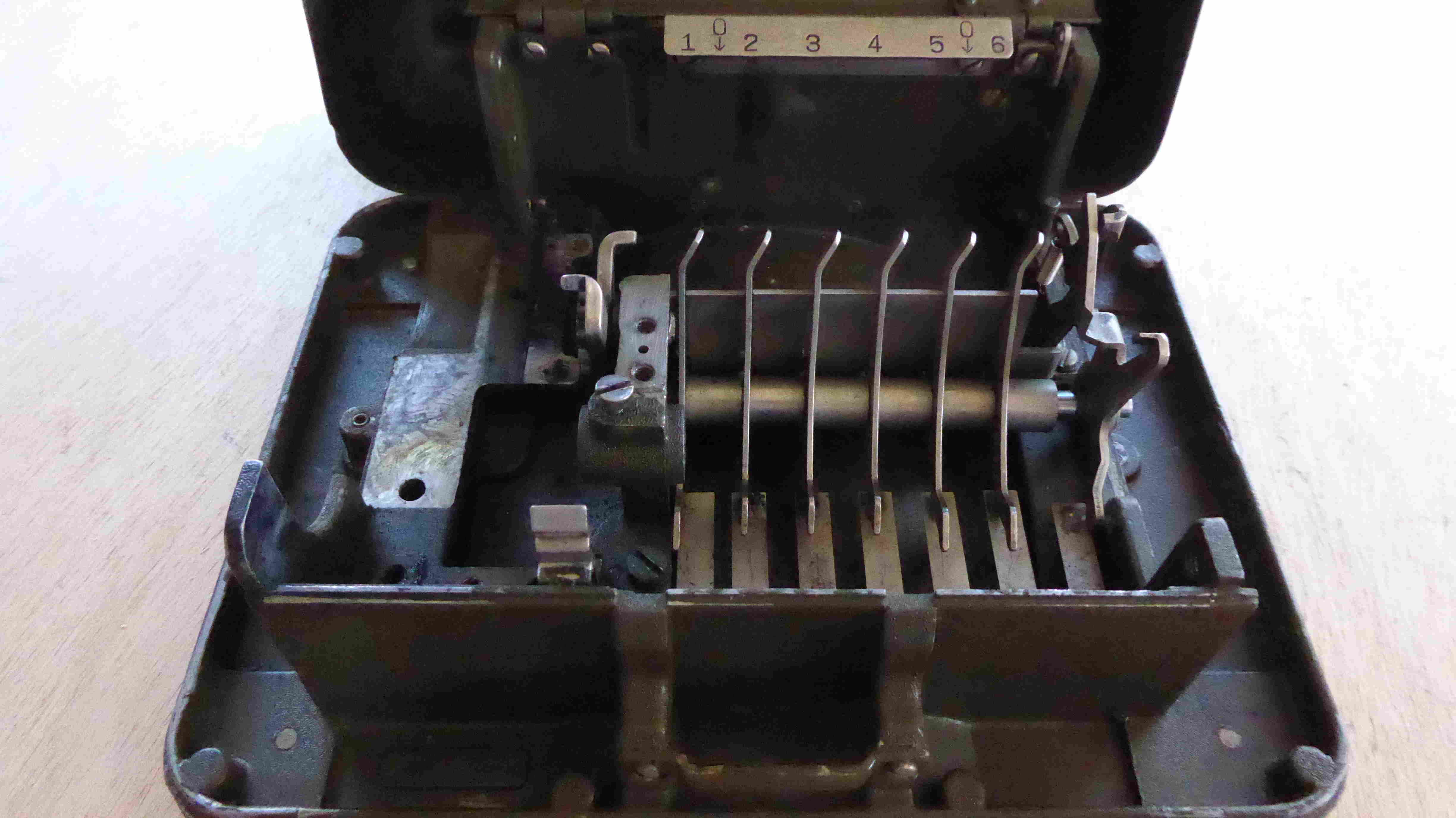
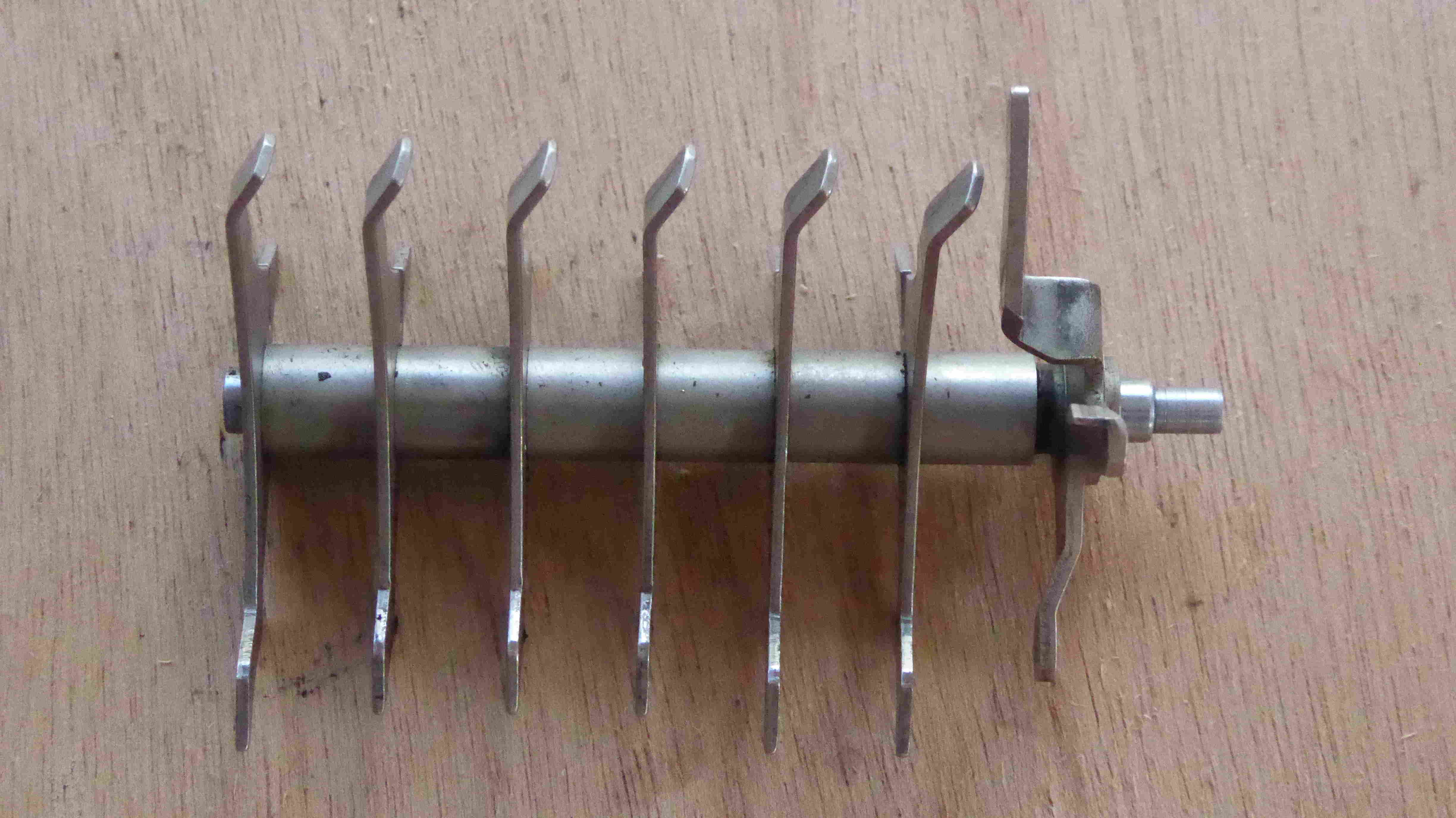
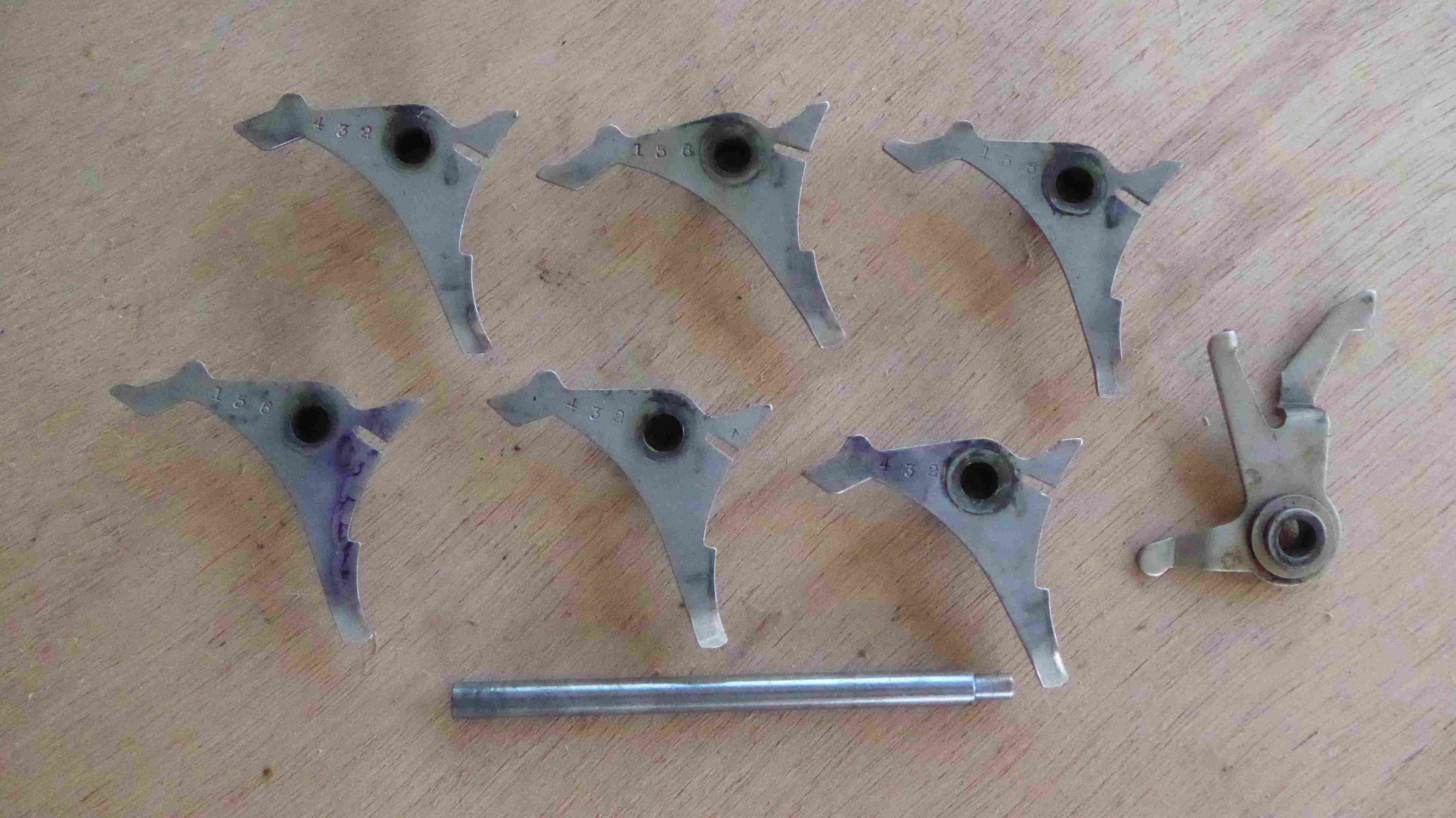
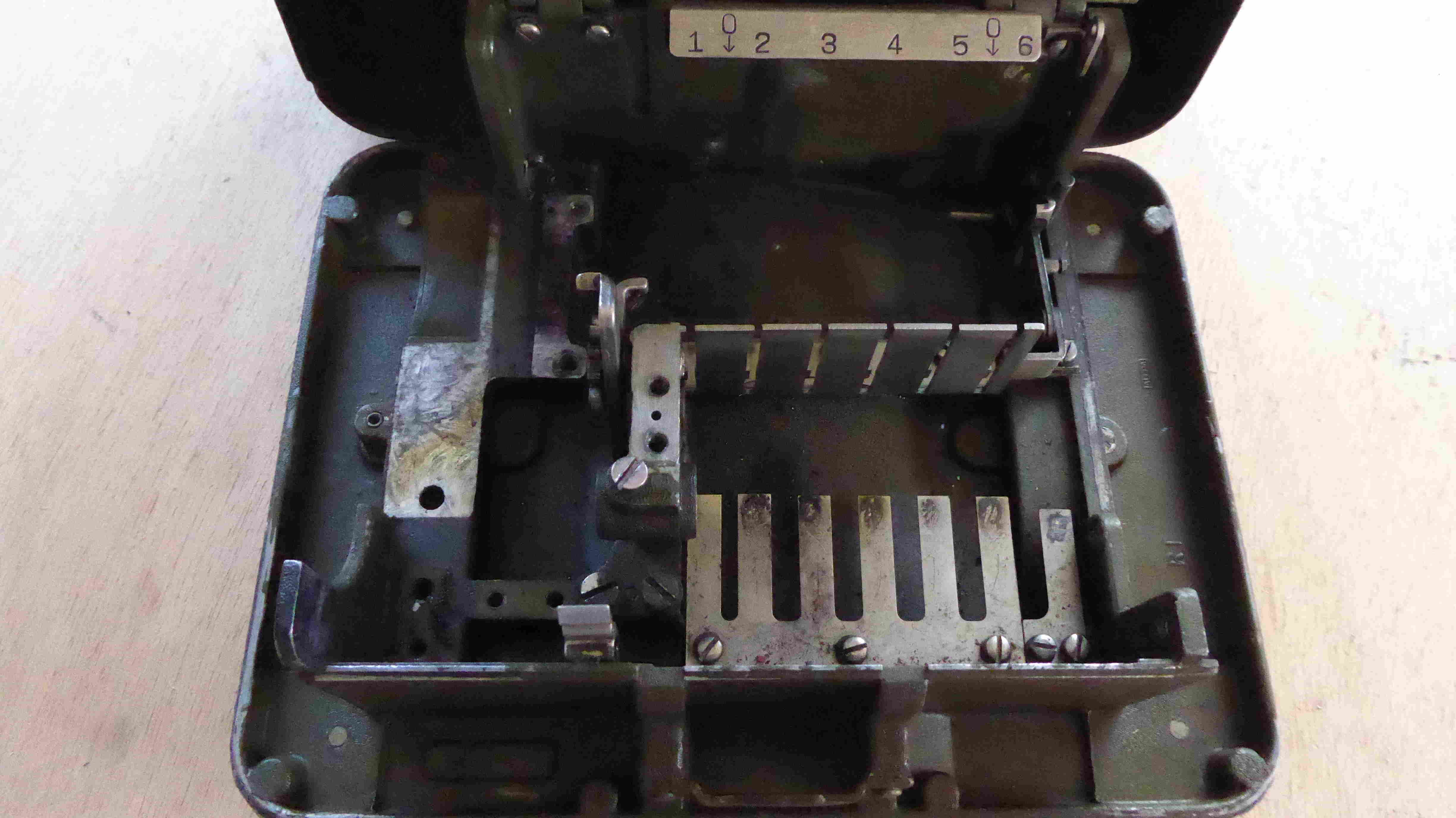
(6) Remove the guide arm shaft, guide arms, and intermediate gear lock (fig. 9).
{see the Manual for following paragraphs}
|
|
|
| Before dismantling | The Right side-plate | After dismantling the Right side-plate |
|
|
|
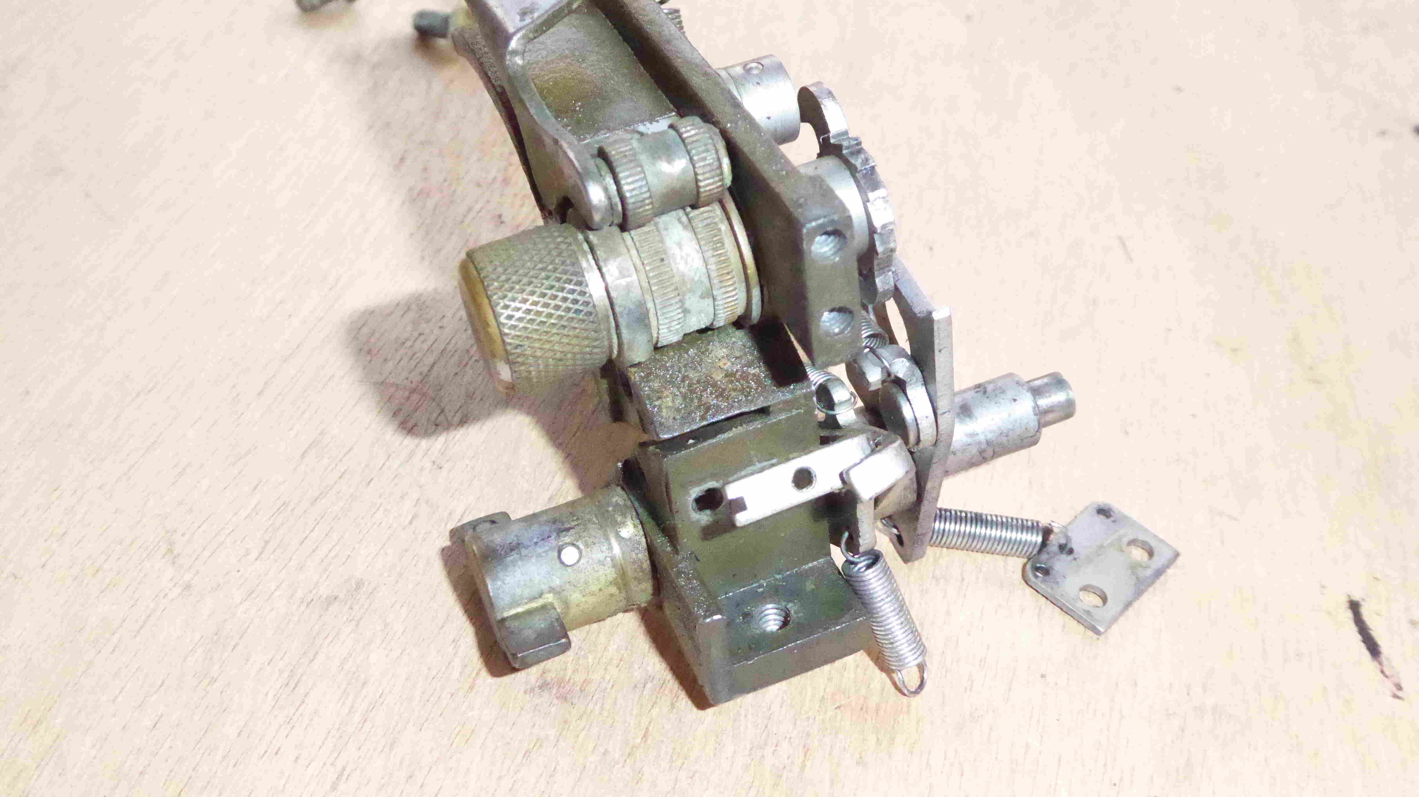
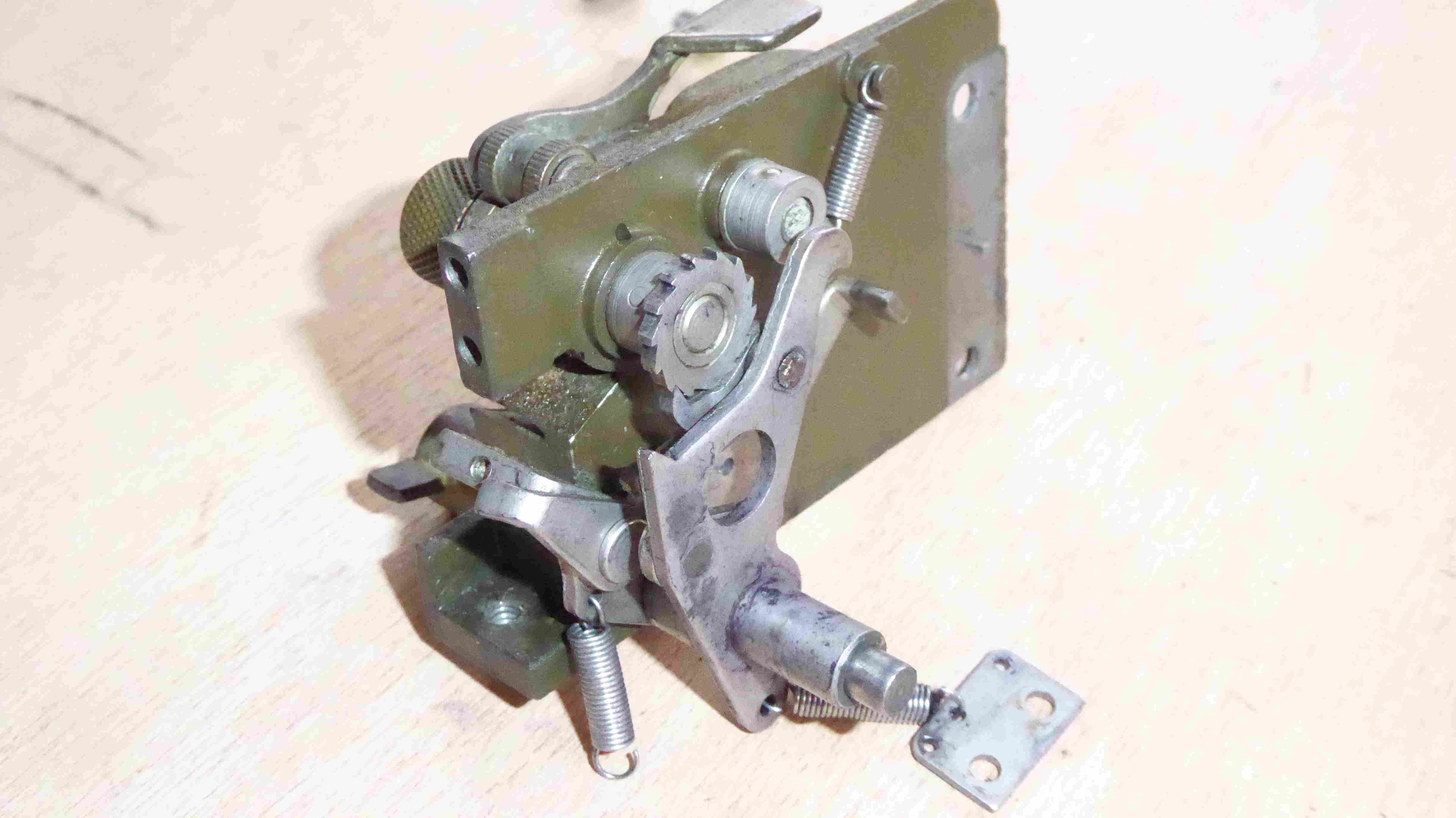
| Before dismantling | Remove the intermediate gear assembly | The intermediate gear assembly |
|
|
|
| Remove the screw ... underside of the base | screw on the lower back of the left side-plate | After Dismantling |
|
|
|
| The left side-plate | The left side-plate | The left side-plate |
|
|
|
|
| The intermediate gear assembly | The intermediate gear and left side-plate | The intermediate gear assembly |
|
|
|
| Before Dismantling | The Drum | After Distmantling |
|
|
|
| The guide arms assembly | shaft, guide arms and intermediate gear lock | After Distmantling |
PROCEDURE FOR REASSEMBLING
To reassemble Converter M-209-(*) follow in reverse order the procedure given above for dismantling ...{see The Manual for more information}
|
|
|
| The left side-plate | The left side-plate | After Reassembly of Drum |
References
- M-209 ManualĀ: TM 11-380, 1944