The Red machine: Working
The Red Home Page
- Introduction
- Working (This Page).
- History
- Genuine messages
- Procedures
- My Simulator
- Cryptanalysis
- SIS's Cryptanalysis
- Challenges
Introduction
No copy of the Type A machine (called RED by the SIS) exists. However, the Americans captured an Orange machine. The following section describes the RED machine as imagined by Rowlett, one of the two SIS cryptanalysts who cracked it (see SIS's cryptanalysis).
| Fig 1: The RED machine |
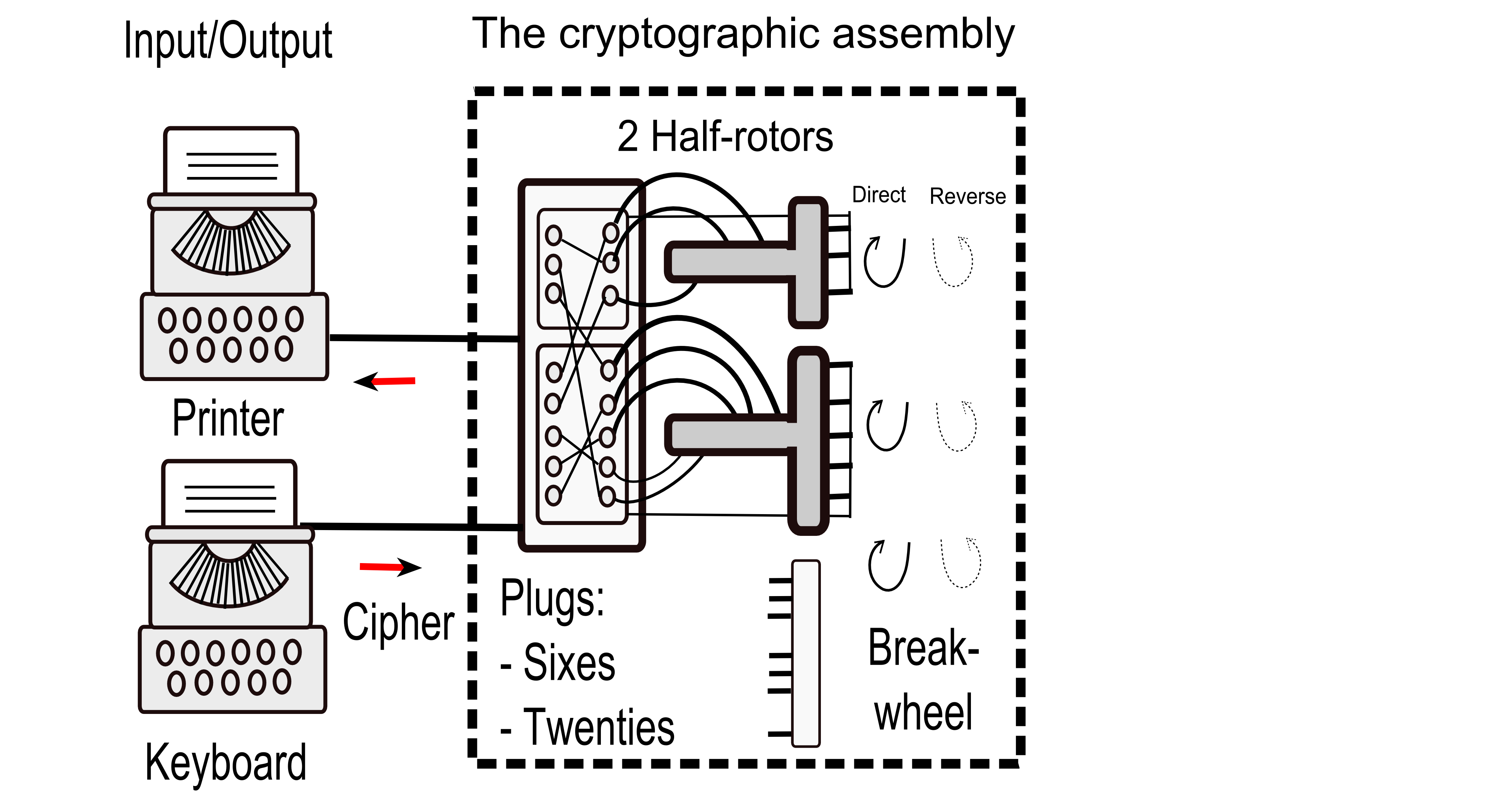
Rowlett's description of the operation of the RED cipher machine
Note: Rowlett calls commutator what we call half-rotor.From a crytanalytic viewpoint, the Japanese diplomatic cipher machine system was composed of three distinct subsystems. One of these was the machine itself, which automatically performed the enciphering and deciphering processes. It consisted of a typewriter keyboard, a cryptographic mechanism, and a printing apparatus. Altough we never saw a model of the RED machine, we suspect that the Japanese had constructed the keyboard and printing mechanism from commercially produced typewriters which they modified to perform the input and output functions of the device.
The little evidence that we developed from the few intercepts that discussed the operation of the device, and from our observations based on our analysis of it as well as the practices followed by the Japanese code room personnel in using it, led us to believe that the cryptographic mechanism was uniquely developed and constructed by the Japanese. As we visualized it, the cryptographic mechanism consisted of a pair of electrical commutators which were geared together and which stepped either forward (direct mode) or backward (reverse mode) with the encipherment of each letter of the message. The movement of these two commutators was controlled by a mechanism which at intervals introduced additional steps into the movement pattern of the commutators.
The cryptographic component was also provided with a plugboard and plug arrangement from which twenty-six pairs of wires led to the keyboard and printing components. This plugboard arrangement allowed the connections between the keyboard and printer to be changed manually by the code-room personnel and was an important keying element in the security of the device. A means was also provided for switching the device from the enciphering mode to the deciphering mode and vice versa. ...
With the machine set in the enciphering mode, the first letter of the message was enciphered by depressing the key on the keyboard corresponding to it. This sent an electical impulse through the plugboard into the commutating mechanism. There it caused the appropriate solenoid to operate, automatically recording the cipher equivalent. On release of the key, the cryptographic mechanism would automatically advance so that a solenoids of the printing mechanism. To encipher the second letter of the message, the key corresponding to it was depressed and its equivalent was automatically recorded; when the key was released, the commutators again advanced to a new position. This process was continued until all the letters of the message wre enciphered. To decipher the message, the plugboard sequence and the settings of the commutators and the stepping mechanism had to be exactly the same as those used for its encipherment, except that the machine had to be orperated in the decipherment mode.
Some details
The Electrical Circuit
The electrical current starts at the keyboard (which could be a typewriter keyboard). It then arrives at a first plugboard (the input plugboard). The current output goes to one or the other of the two half-rotors. Let's say the current arrives at the first letter of the Sixes. After the Sixes half-rotor, the current exits at the input of the second plugboard, which is wired exactly as the inverse of the first. The current arrives (for example) at the second letter of the Sixes, which exits from the second plugboard (for example) as the fifth letter of the Twenties, and ends up on the light board (or the printer part of a second typewriter).
In fact, the two logical plugboards are easily the inverse of each other because they correspond to a single physical plugboard. Each plug contains two cables: one belonging to the first logic plugboard (which carries current from one input/output device to the input of a half-rotor), the other belonging to the second logic plugboard (which carries current from the output of one half-rotor to the other input/output device).
A lever is located between the input/output devices (which are typewriters in the case of the Japanese typewriter) and the physical plugboard. It allows the circuits to be switched to switch from encryption mode to decryption mode.
Rotor advancement
The advancement of the half-rotors (commutators) is controlled by the Breakwheel, which has 47 pins on its periphery. If pins are removed, the advancement of the half-rotors is increased proportionally. Thus, if a Pin that is in the active position (it affects the advancement) is removed, the half-rotors advance two steps instead of one.
Differences between the Japanese machine and its American copy
American cryptanalysts, in their analog machine, used two half-rotors (one for the Sixes, the other for the Twenties). In fact, the Japanese machine used only one half-rotor which was composed of 60 contacts (the lowest common multiple of 6 and 20 is equal to 60), a bit like the paper simulator which was composed of two crowns of 60 letters, one composed of the Twenties in triplicate and the other of the Sixes in ten copies.
For input/output devices, the Japanese used typewriters. The Americans used a single keyboard from a typewriter for input, but for output they initially used a light panel and later the printer part of a typewriter.
The components of a key
- The Plugboard Configuration:
- Plugboard for the Sixes
- Plugboard for the Twenties
- The Removed PINS
- The Starting Position of the Wheels:
- Breakwheel
- Half-Rotor of the Sixes
- Half-Rotor of the Twenties
- The Encryption or Decryption Mode
- The direct or Reverse Mode (Direction of Wheels Movement)
Period
We've already calculated the period for which the Sixties and Twenties return to phase: 60. For the full period, we multiply this value by the Breakwheel period, which has a value between 36 and 47. In short, the period has a value between 2160 and 2820.
Examples
First example
We can demonstrate how the cipher works by taking two sets of letters (the Sixes and the Twenties) that are shifted by one position with each ciphering operation. The Sixes and the Twenties remain synchronous.
In the example below, the Sixes and the Twenties are doubled.
Note: The paper simulator used by the SIS uses the same principle as the one below, but it is simpler to use because it is circular.
KeyĀ:
- SIXESĀ: TBZJNR
- TwentiesĀ: SKYMPIHLDVWAOFQCXUEG
- The other parts of the key used the default values (mode ciphering, mode direct, start position of the wheelsĀ: 1,1,1, no pins was removed)
PlainĀText : TO BE OR
CryptogramĀ: TA RC DT
V
SKYMPIHLDVWAOFQCXUEGSKYMPIHLDVWAOFQCXUEG
SKYMPIHLDVWAOFQCXUEGSKYMPIHLDVWAOFQCXUEG
TBZJNRTBZJNR T=>T
TBZJNRTBZJNR
V
SKYMPIHLDVWAOFQCXUEGSKYMPIHLDVWAOFQCXUEG O=>A
SKYMPIHLDVWAOFQCXUEGSKYMPIHLDVWAOFQCXUEG
TBZJNRTBZJNR
TBZJNRTBZJNR
V
SKYMPIHLDVWAOFQCXUEGSKYMPIHLDVWAOFQCXUEG
SKYMPIHLDVWAOFQCXUEGSKYMPIHLDVWAOFQCXUEG
TBZJNRTBZJNR B=>R
TBZJNRTBZJNR
V
SKYMPIHLDVWAOFQCXUEGSKYMPIHLDVWAOFQCXUEG E=>C
SKYMPIHLDVWAOFQCXUEGSKYMPIHLDVWAOFQCXUEG
TBZJNRTBZJNR
TBZJNRTBZJNR
V
SKYMPIHLDVWAOFQCXUEGSKYMPIHLDVWAOFQCXUEG O=>D
SKYMPIHLDVWAOFQCXUEGSKYMPIHLDVWAOFQCXUEG
TBZJNRTBZJNR
TBZJNRTBZJNR
V
SKYMPIHLDVWAOFQCXUEGSKYMPIHLDVWAOFQCXUEG
SKYMPIHLDVWAOFQCXUEGSKYMPIHLDVWAOFQCXUEG
TBZJNRTBZJNR R=>T
TBZJNRTBZJNR
Here is the result of the encryption using my computer simulator:
$ echo TO BE OR | python3 red_tui.py -G TBZJNRSKYMPIHLDVWAOFQCXUEG -D
...
  1: ( 1, 1, 1) Plain: T(19)-> Plug:  1  Sixes A => After HRVOY: A ( 1)  Crypto: T (19)
  2: ( 2, 2, 2) Plain: O(14)-> Plug: 13  Twent Q => After HRCON: P (12)  Crypto: A ( 0)
  3: ( 3, 3, 3) Plain: B( 1)-> Plug:  2  Sixes E => After HRVOY: Y ( 6)  Crypto: R (17)
  4: ( 4, 4, 4) Plain: E( 4)-> Plug: 19  Twent X => After HRCON: T (16)  Crypto: C ( 2)
  5: ( 5, 5, 5) Plain: O(14)-> Plug: 13  Twent Q => After HRCON: L ( 9)  Crypto: D ( 3)
  6: ( 6, 6, 6) Plain: R(17)-> Plug:  6  Sixes Y => After HRVOY: A ( 1)  Crypto: T (19)
TARCDT
Second example
If pins are removed, the Sixes and Twenties no longer advance regularly. Occasionally, one or two letters are skipped. On the page describing two authentic messages, the first message is shown sliced into 41-letter segments (6 pins are removed). For each segment, the plaintext, the cryptogram, and the position of the removed pins are indicated.
Other examples
The first challenge (link) contains additional examples. However, the half-rotors correspond to the wiring provided by Konheim.
Note: It seems that the half-rotors of the RED cipher machine uses Vigenere-style direct wiring. When I created my RED Challenge, I based it on Konheim's writings, I had not seen any authentic RED messages.
References
Books and Articles
- Machine Cryptography and Modern Cryptanalysis, by Cipher A. Deavours and Louis Kruh, Artech House, INC, 1985.
- Computer Security and Cryptography, by Alan G. Konheim, Wiley, 2007.
- The Story of Magic, by Frank B. Rowlett, Aegean Park Press, 1998.
Internet
- Tomokiyo - Development of the First Japanese Cipher Machine: RED (link)