HCM 5 rotors description
The Hebern rotors machine (HCM)
- HCM 5 rotors home page
- HCM description (this page)
- Genuine messages
- Navy 1924 Challenge
- Poem
- Cryptanalyse
- Friedman's report
- Simulator
- Emulator in paper
- Challenges
HCM electrical description
 |
 |
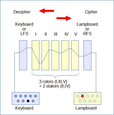
The Hebern Cipher Machine (HCM) consisted essentially of six electrical components, as follows:
- A keyboard similar to a typewriter keyboard.
Pressing a key on the keyboard closes an electrical circuit. - The wiring coming from the keyboard and arriving at the left rotor input (in position I) does not follow alphabetical order. As a result, this wiring acts as a sort of stator (a rotor that does not move forward). Knowledge of this wiring is necessary to be able to emulate encryption. Friedman calls this wiring Keyboard or LFS.
- A set of five rotors working in cascade that provides encryption and decryption (by swapping letters).
- The wiring coming from the right rotor output (in position V) and arriving at the lamp input does not follow alphabetical order. As a result, this wiring acts as a sort of stator (a rotor that does not move forward). Knowledge of this wiring is necessary to be able to emulate encryption. Friedman calls this wiring Lampboard or RFS.
- A lampboard which is a bank of twenty-six illuminated lamps. Each lamp represents a letter of the alphabet. When an electrical circuit is closed, the lit lamp represents the ciphered letter (or a plain text letter if we had keyed a ciphered letter).
- A cipher-decipher switch. This switch reverses the current.
In the cipher mode (or DIRECT mode), the enciphering current flowed from left to right and passes through the keyboard, the five rotors and the lampboard. In the decipher mode (or REVERSE mode), the deciphering current flowed in reverse direction from the lampboard to the keyboard. Remark: One can cipher in the deciphering mode, then the mode (ciphering or deciphering) is part of the key. The rotors are inserted into the machine in a prescribed daily order known to both correspondents. The rotors could even be inserted backwards, So the five rotors are equivalent to ten rotors.
The ratchets wheels and advancement of rotors
Advancement of rotors (principles)
The HCM consisted essentially of four mechanical components:
- Keyboard keys. When you press a key, you (at least) advance the right rotor and the right ratchel wheel. Depending on the position of the ratchel wheels, the left rotor and the one in the middle can move forward.
- Two ratchet wheels.
- Several ratchets triggered by ratchet wheels. They act to move the rotors.
- The movable rotors in positions: I,III,V. Note: The rotors in positions II and IV are stationary during encryption. We can just choose them from the pool of rotors and insert them into slots and choose their position and if it is in normal sense or inverted.
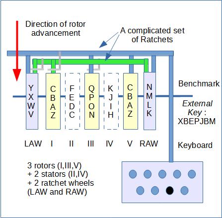
The advancement of the rotors according to Deavours & Kruh
On the extreme left was the left ratchet wheel followed by the five rotors which we denote I, II, III, IV and V, followed by the right ratchet wheel. As each letter of the plaintext was depressed on the keyboard, rotor V (the fast rotor) stepped one position forward (before encipherment). The right ratchet wheel also advanced one step with each letter enciphered.
When the right ratchet wheel reached the letter N on the machine’s benchmark, the ratchet arrangement then caused both the left ratchet wheel and rotor I (the medium rotor) to advance one step. Thus, after the first time, N is reached on the right ratchet wheel, the left ratchet wheel and rotor I are stepped once for each revolution of rotor V.
The left ratchet wheel drives rotor III (the slow rotor) whenever it reaches N on the benchmark in a similar manner.
The rotors II and IV are stators.
The advancement of rotors (Example from Deavours & Kruh)
A sample rotor movement starting at the External key MEANING is show below (LAW=Left ratchet wheel, RAW=Right ratchet wheel, I,II,III,IV,V=the rotors):
    LAW I   II  III IV  V   RAW
    M   E   A   N   I   N   G
    M   E   A   N   I   O   H
    M   E   A   N   I   P   I
    M   E   A   N   I   Q   J
    M   E   A   N   I   R   K
    M   E   A   N   I   S   L
    M   E   A   N   I   T   M
    M   E   A   N   I   U   N
    N   F   A   N   I   V   O
    N   F   A   O   I   W   P
    N   F   A   O   I   X   Q
    N   F   A   O   I   Y   R
    N   F   A   O   I   Z   S
Key size
The overall period of the machine is not the maximal one of 26x25x26 letters because the slow rotor moves every 650 letters instead of every 676 letters (26x26) as a result of the rachet arrangement used. The period is therefore of 650x26 = 16900.
The wiring of the rotors, keyboard and lampboard of Army machine
	Keyboard:  XAKHSZJLYWGPMIOURDBFTNVCQE (LFS)
	Rotor 1:   GADBOCTKNUZXIWHFQYJVPMELSR
	Rotor 2:   IZNCTKUDPJEVOWLFHXSMGQAYBR
	Rotor 3:   PJXFWLTAUGYBMHROVNCKSEQIZD
	Rotor 4:   FLVARGWCMQBXNYIOTJUPSKEDHZ
	Rotor 5:   FQTGXANWCJOIVZPHYBDRKUSLEM
	Lampboard: TYOEUMXDFJQVKWBNSHCILRZAGP (RFS)
Keying (summary)
The key is made up of two parts:
- The daily key is itself made up of several parts:
- In what order are the 5 rotors positioned and for each, the positioning direction: normal or backwards.
- The direction of the electric current: DIRECT (the electric current passes through the rotors from left to right) or REVERSE (current flows through the rotors from right to left).
- The message key is composed of the starting position of the 7 wheels: The two ratchet wheels and the 5 rotors, for example MEANING.
Note: The Keyboard (RFS) and Lampboard (LFS) wiring cannot be modified. They are part of the basic key. Only capture (or purchase) of the machine allows you to know them.
Mathematical formula
The enciphering equation of the Hebern machine is:
\( pKC^{i}UC^{-i}C^{j}VC^{-j}C^{k}WC^{-k}C^{l}XC{-l}C^{l}C^{m}YC^{-m}L = c \)
A plain letter: p, the cipher letter: c.
The rotors are at positions i, j, k, l, m.
K represents the Keyboard permutation.
L represents the Lampboard permutation.
The permutations of rotors I-V are represented by U, V, W, X, Y.
C is the circular shift (Caesar permutation).
Note: See the following page to understand the mathematics of a rotor.
References
- Machine Cryptography and Modern Cryptanalysis, by Cipher A. Deavours & Louis Kruh, Artech House Editor, 1985. This book describes in detail the operation of the 5-rotor HCM.
- Rotor Algebra, by James Reeds, Cryptogia, Vol 1, N°2, April 1977.
Web Links
- ANALYSIS OF A MECHANICO-ELECTRICAL CRYPTOGRAPH,
PART I, TECHNICAL PAPER,
BY WILLIAM F. FRIEDMAN
Cryptanalyst, Chief of Signal Intelligence Section
UNITED STATES GOVERNMENT PRINTING OFFICE,
WASHINGTON: 1934, Secret.
(link)
Note: Probably written in 1924. The work has remained classified over 60 years old, maybe it is yet classified?