French Army C-36: Machine operation
( )
(
)
( )
)
C-36 Home Page
2. Introduction
The French C-36 operates globally as do all of the Hagelin C-series machines, of which the best known representative is the American M-209. The C-36 is arguably the smallest pre-war (and war) period cipher machine: 18 x 13 x 7.5 cm (7.1 x 5.1 x 2.9 in) and its weight is not excessive: 2.47 kg.
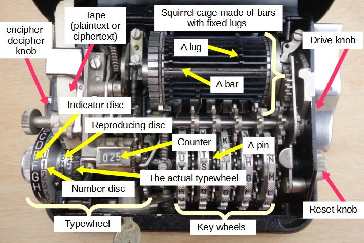
A Hagelin C-series machine is essentially comprised of three elements (cf. Figure 1, below):
- The typewheel.
- The drum (called the "squirrel cage" by the French).
- The key wheels.
| Fig 1: The C-36, the differents parts |
2.1 The typewheel use, mathematical vision, and setting
The most important component of the Hagelin C-series machines is the typewheel. The part that is visible has an indicator disc on which the 26 letters of the alphabet are written. The part that is invisible comprises the typewheel proper: it is this which is used to print the encrypted letter (or the plain one). It also contains the 26 letters of the alphabet, but in the reverse order to that of the indicator disc. The typewheel is duplicated on the reproducing disc. Only one letter of this disc is visible and corresponds to the encrypted (or decrypted) letter. This wheel allows the machine to be used even when the printing component no longer works (through lack of paper or ink pads).
To encrypt, the user places the letter to be encrypted in front of a benchmark by rotating the indicator disc. Then, using a lever located on the right side of the machine (the drive knob), the shift mechanism is activated. Together, the indicator disc and the type wheel rotate in the same direction for as many letters as the value of the offset. When stopped, the encrypted letter is printed on a strip of paper and is visible on the reproducing disc. We have, in fact, just witnessed that the Hagelin C-series uses the Beaufort cipher, which is a special form of the Vigenčre cipher in which the key is subtracted from plaintext. The advantage is that encryption and decryption are identical:
	C = D - P
	P = D - C

	C = Ciphered letter
	P = Plain letter
	D = Difference
The difference D is divided between the slide (S) and the key stream (K) generated by the internal configuration activated by the drive knob. For the M-209, slide is fixed and set to 25. For the C-36, slide is internally adjustable and part of the internal key. For the C-446 and C-38, slide is externally adjustable and part of the external key (message key).
	C [i] = (S + K [i]) - P [i]
	P [i] = (S + K [i]) - C [i]

	P [i] = The numeric value of the ith plain letter,
	C [i] = The numeric value of the ith ciphered letter,
	K [i] = The ith key.
Note: The archives do not provide the official method used to change the slide. I managed to modify the slide by rotating the indicator disc after blocking the typewheel. This operation was not easy and may not correspond to the recommended procedure. Another technique was to press on a ball, which seemed to block the typewheel (cf. 2.5).
The French C-36 has a peculiarity that distinguishes it from other Hagelin C-series machines; it has a disc comprised of 26 digits in its visible component, which is attached to the typewheel. Hence, its offset is variable and depends on the slide! This disc makes it easy to encrypt numbers. In the procedures used during WWII, a number started with the letter W and ended with the letter K (which codes space)[1]. Thus, the numbered group WUSRK corresponded to the number 421 with a slide of 0 and to the number 154 with a slide of 3.
Example (with an offset of 0): Note: The letter K on the indicator disc is in red, while the number opposite it is hidden. It is logical: the letter K ending a numeric group cannot have a numerical equivalent. The number 1, which is next to the number 6, is also in red. The explanation for this setup will be provided later (cf. 6.3.5.4).
    ABCDEFGHIJKLMNOPQRSTUVWXYZ Indicator disc
	09876543210123456123456789 Number disc
	AZYXWVUTSRQPONMLKJIHGFEDCB Typewheel
Footnote:
[1] In the clear text, the letter K is replaced by QU or CQ
(cf. 5.3.4), and
the letter W is replaced by VV (this procedure was used by the French army
during the 1980s and probably also during the war but I have no proof that
this was the case).
2.2 Internal components: the key wheels
In the previous chapter, we noted that the encryption was produced by the following formula:
C[i] = (S + K[i]) - P[i],where K[i] is the shift related to the encryption (or decryption) of the ith letter. But how is the value of K produced?
The value of K results from the combined action of the squirrel cage and the key wheels. The configuration of the key wheels constitutes (with the slide) the internal key.
A key wheel is a disc divided into a number of sectors. The sector is the unit of angular displacement performed at the end of the encryption of each letter. Each sector is identified by a letter. In each sector a pin is plugged that protrudes on either one face or the other. A pin is active when it intervenes in the production of offsets (in the C-36, a pin that protrudes to the right is active). Periodically (every day, every week, or every month), the operator positions the pin of the wheels based on a key table.
A Hagelin C-series machine is made up of several key wheels, the number of sectors of which are relatively prime numbers. On most Hagelin models (C-38, M-209, C-446, C-52 … ), there are six key wheels. On the C-36, there are only five key wheels, which from left to right have 25, 23, 21, 19, and 17 sectors, respectively. The length of the key is therefore 25 x 23 x 21 x 19 x 17 = 3,900,225. Thus, it is necessary to encrypt almost 4 million letters before the same sequence of shifts occurs again.
The message key (or external key) corresponds to the initial position of the key wheels before the encryption (or decryption) of a message. It is composed of a chain of five letters in the case of the C-36. When the internal cover is closed, parts of the key wheels are still visible, which allows the operator to turn each wheel and position the message key by aligning the letters of which it is composed in front of a mark (cf. Table 1).
The pins acting on the shifts do not correspond to the visible alignment of the wheels. There is a constant but different offset for each wheel between the sector associated with the letter visible on the outside and the sector that contains the pin that acts on the shift. For the C-36, the acting pins are JIHHG if the visible letters are AAAAA. In the case of the M-209, the acting pins are PONMLK if the visible alignment is AAAAAA.
Table 1: The reference letters of the five key wheels of the C-36
	25-sector wheel: ABCDEFGHIJKLMNOPQRSTUVXYZ
	23-sector wheel: ABCDEFGHIJKLMNOPQRSTUVX
	21-sector wheel: ABCDEFGHIJKLMNOPQRSTU
	19-sector wheel: ABCDEFGHIJKLMNOPQRS
	17-sector wheel: ABCDEFGHIJKLMNOPQ
	Note: Note the absence of the letter W.
2.3 Internal components: the squirrel cage
The squirrel cage [1] is a cylinder made up of several bars: 25 in the case of the C-36, 27 in the case of the M-209, and 32 in the case of the CX-52. Each bar has one or two fixed or mobile lugs. Each lug is (or can be) placed in front of a key wheel. In most of the Hagelin C-series machines (C-38, M-209, C-446, CX-52 … ), the lugs are mobile. Their position is thus a component of the internal key. In the case of the C-36, the lugs are fixed, [2] and their position is a secret part of the machine (basic key).
When the operator acts on the drive knob, they turn the cage one full turn.
The key wheels are connected with the squirrel cage by guide arms. There are as many guide arms as there are key wheels.
During encryption, the active pins come into contact with one of the ends of the guide that correspond to them and push them forward, and they are then in the active position. The active guides come into contact with the lugs placed in front of them and push them and the bar that supports them to the left. The left end of the shifted bars then protrudes and turns the typewheel a notch. The number of shifted bars corresponds to the shift K[i].
Footnotes:
- [1] The squirrel cage is referred to as a drum in the documentation for the M-209.
- [2] In the case of the C-36 M2, which represents an upgrading of the C-36 made in the 1950s, the lugs are movable. As for the M-209, there are two per bar (cf. 7.3).
2.4 The encryption and decryption modes
Unlike the B-211 cipher machine, the encryption and decryption are identical for all of the Hagelin C-series machines. However, these machines have a button that allows the user to choose mode C ("Chiffrement": encryption mode) or D ("Déchiffrement": decryption mode). The mode only acts on printing. In encryption mode, the cipher text appears as a series of groups of five letters. In decryption mode, the plain text appears as words separated by spaces. On the C-36, if the operator encrypts the letter K, a space will appear on decryption. On the M-209, the letter Z is used to create spaces. On the CX-52, the user can choose any letter to represent a space.
2.5 The C-36 in pictures
 |
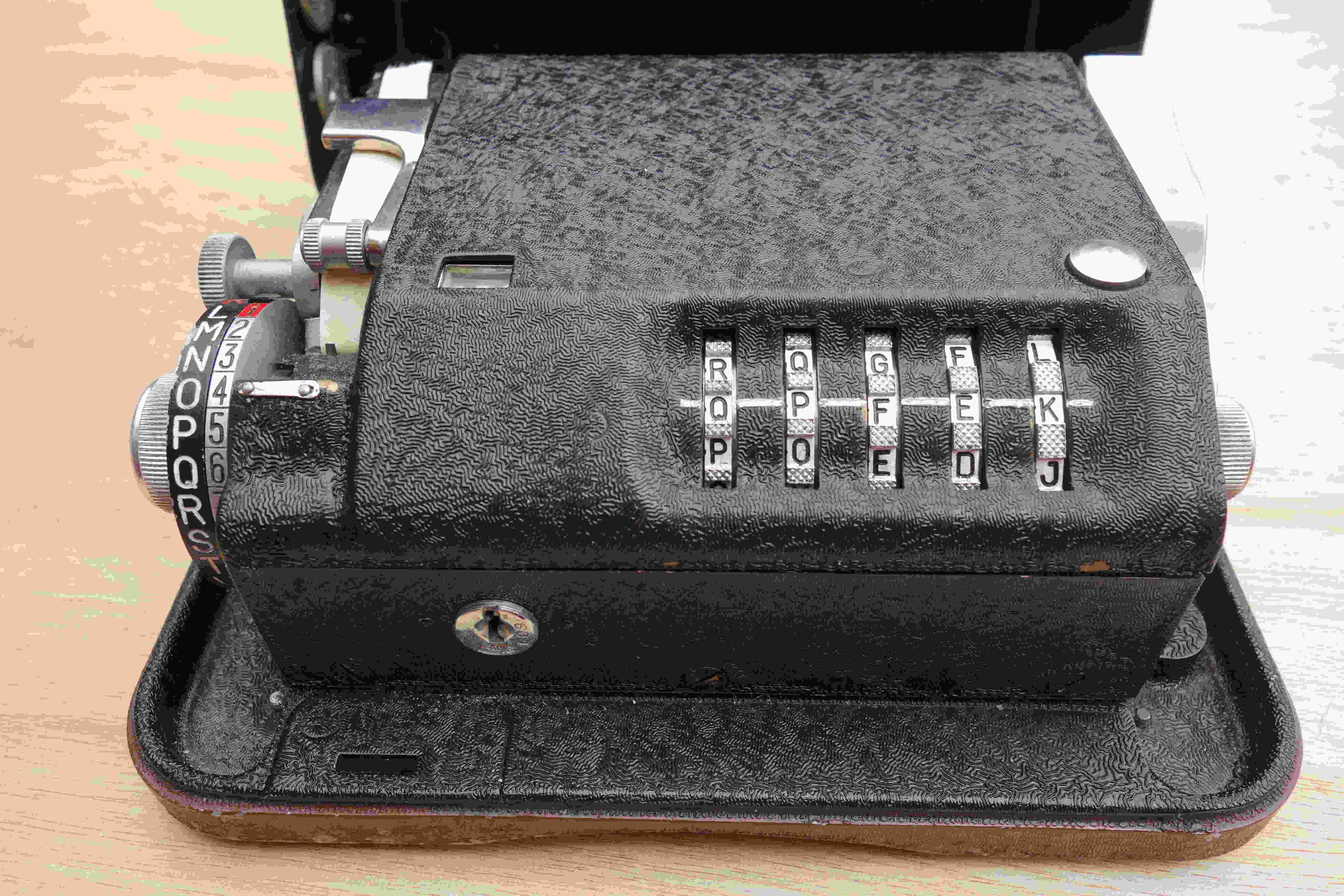 |
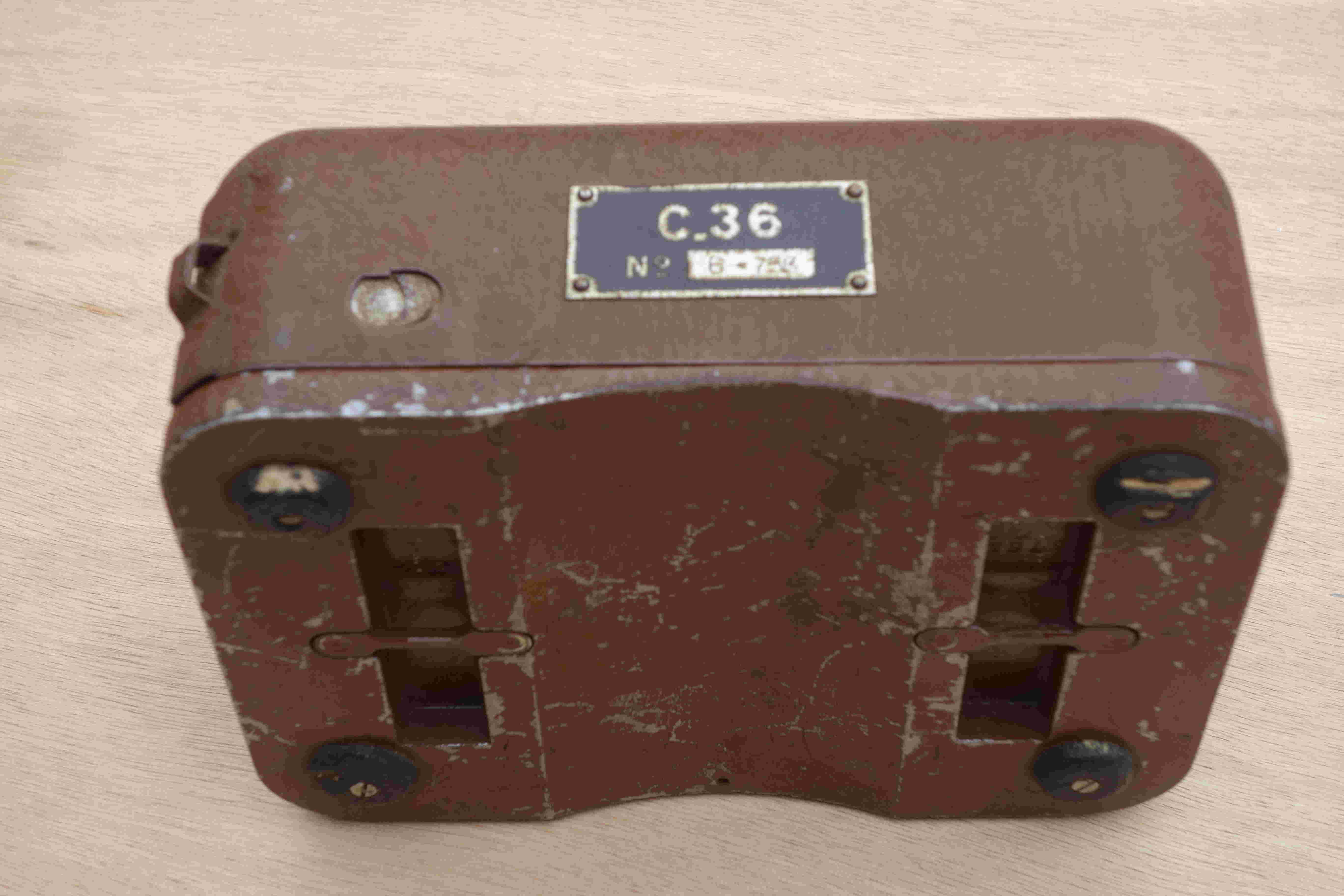
Figure 2 shows the exterior of the machine and therefore the outer cover that protects it. On the front, we can see its identification plate, which contains the name of the machine (C.36) and its serial number (6-753). We can also see the latch on the left that allows the cover to be opened (no key is necessary). On the left side, one of the two fasteners that allow the attachment of the carrying strap used to transport the machine is visible. This strap can also be attached to the underside of the machine, which helps keep the machine on the operator's knee when used outdoors.[1]
Figure 3 shows the machine ready for use. The external key is positioned at the benchmark level at QPFEK. On the right, we can see the reset knob which allows the operator to return to the starting key and thus reset the counter to zero. To be able to activate the reset knob, the operator must press the reset button on the top of the cover on the right. On the front of the machine is a lock. One of the two keys provided is used to operate it and thus to access the internal elements, which is necessary to position the internal key.
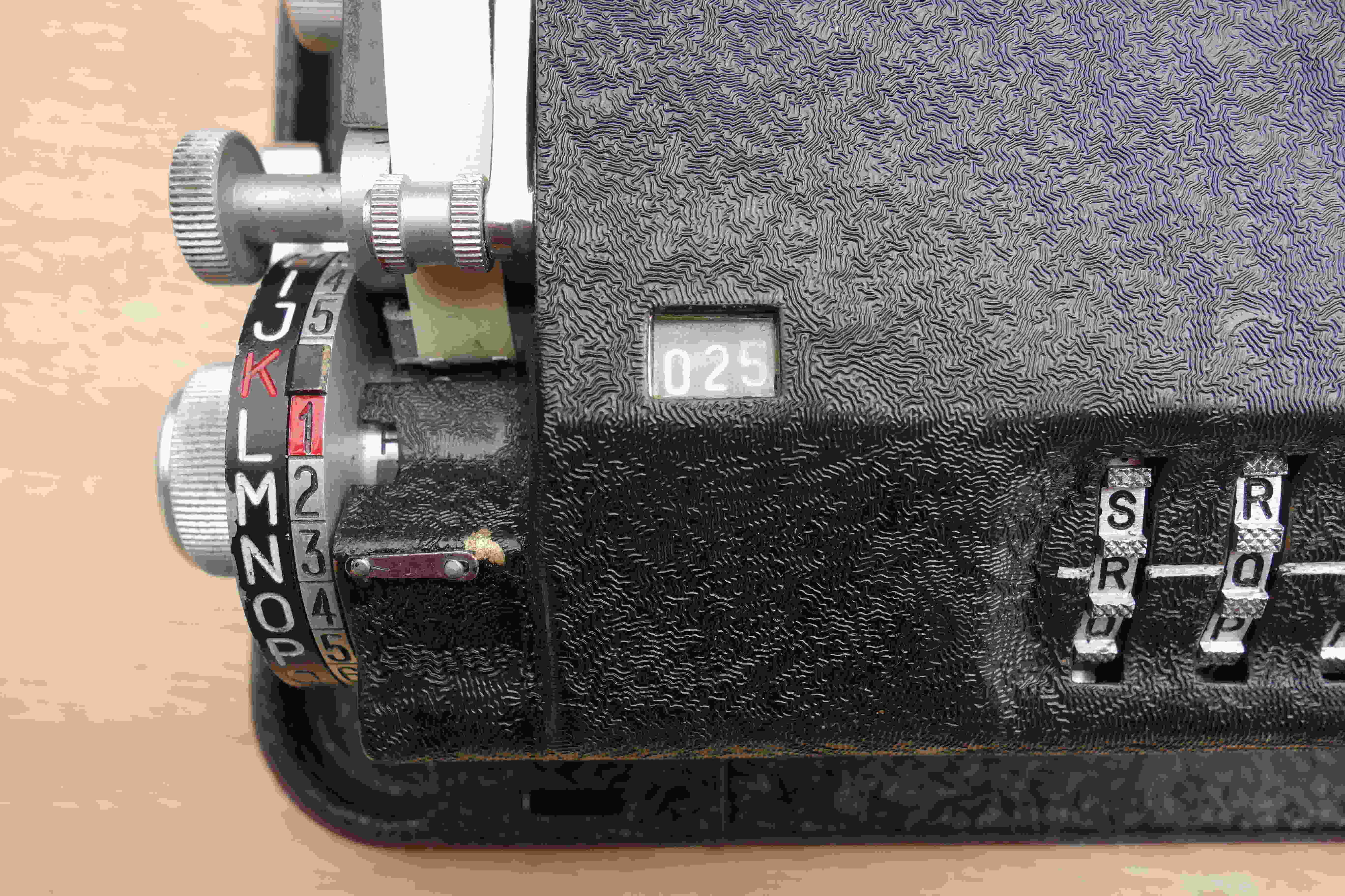
Figure 4 shows the left side of the machine. In front of the benchmark, the letter N is positioned on the indicator disc. If the operator has not yet operated the drive knob, this letter corresponds to the letter that will be encrypted (or decrypted). It is the number 3 that we will encrypt if we are ciphering a number. If the operator has already operated the drive knob, the encrypted (or decrypted) letter is printed and also appears on the reproducing disc. In the figure, it is the letter H. The start of the external key is RQ and the counter is set to 025. On the indicator disc, the letter K is in red, and the number next to it is hidden. [2] The number 1 is in red, and the letter facing it is L. It is the letter that sets the slide (cf. 6.3.5.4). Above the typewheel, we can see the button that advances the strip of paper. Under this button, we can see ("barely") the encipher-decipher knob.
 |
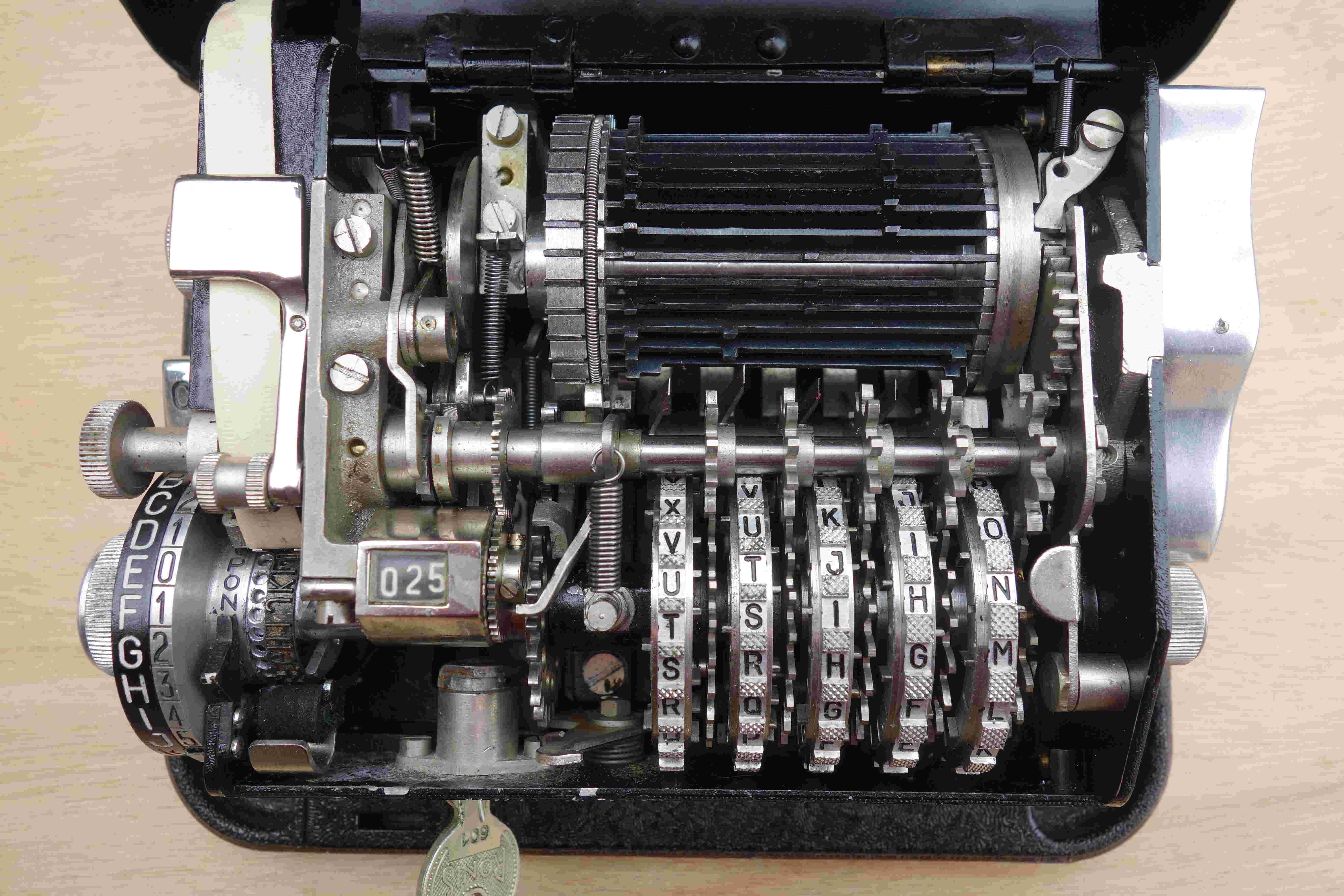 |
Figure 5 shows the inside of the machine. The first figure (Fig. 1) provides the names of the visible components (typewheel, key wheels, squirrel cage,…). On the left, we can see that the encipher-decipher knob is positioned in encryption mode (letter C). By activating this knob, the machine can now be placed in decryption mode (letter D). To the right of the reproducing disc, there is a ring with holes. Opposite the letter N, we can see (barely) the ball that blocks the slide. To change the slide, this ball has to be pressed.
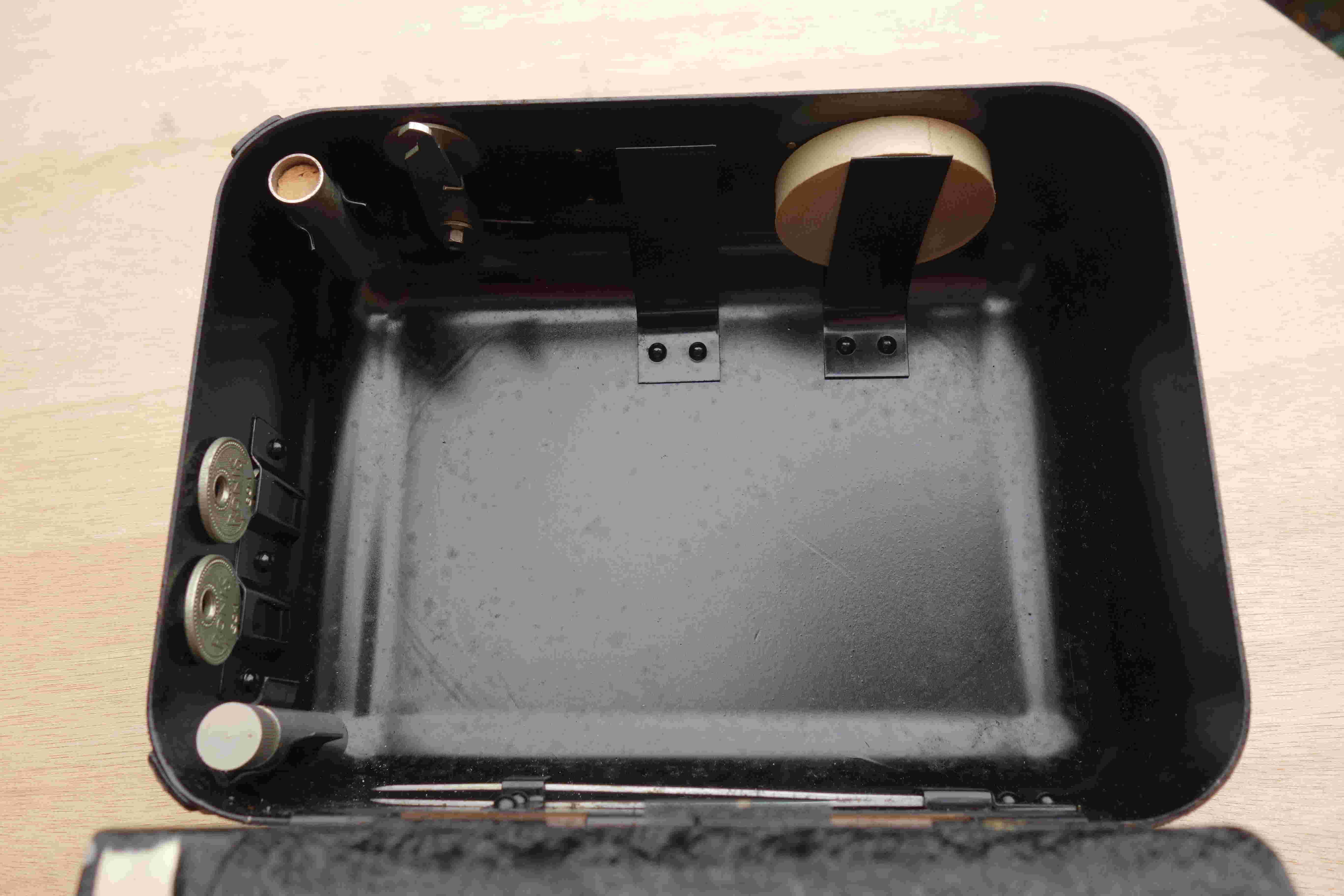
Figure 6 shows the inside of the machine cover. This cover contains the machine's utensils: at the top, there are two spare rolls of paper. On the left side, there are two tubes: the oil can and the ink pad can (closed with a cork stopper). There are also two keys that allow the inner lid to be opened. At the bottom, we can see the tweezers.
 |
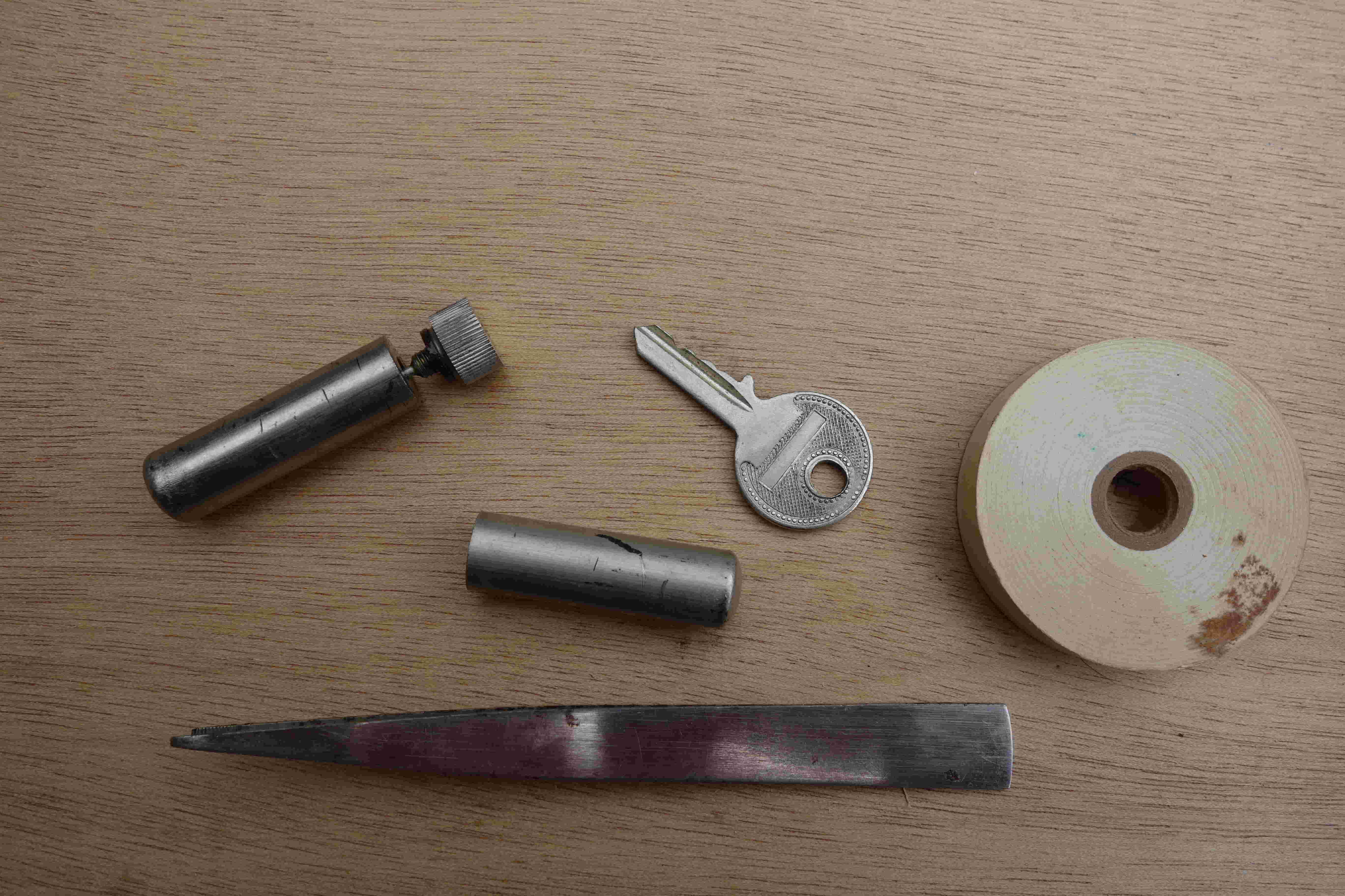 |
Figure 7 shows some of the utensils described above.
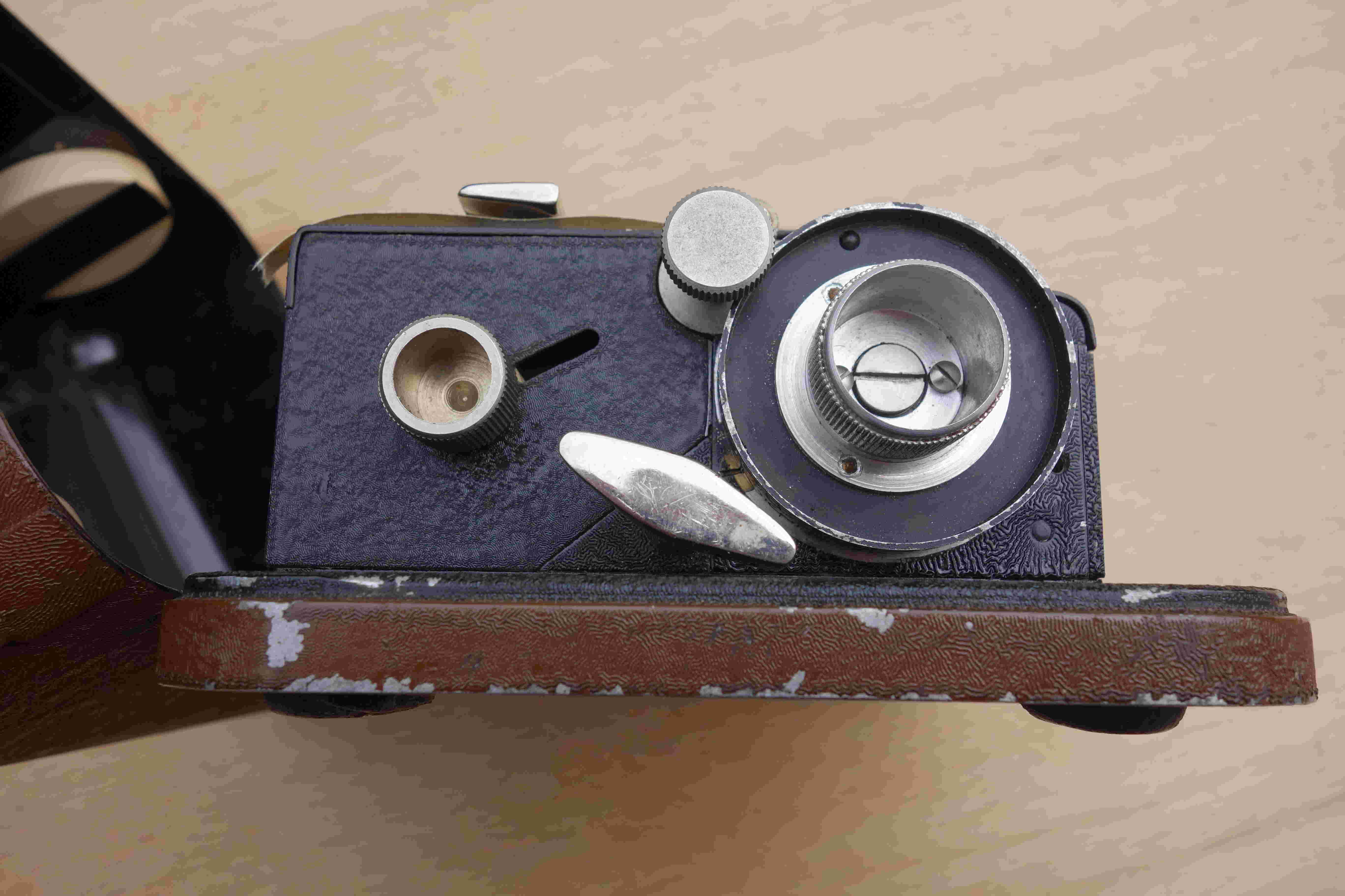
Figure 8 shows the left side of the machine.
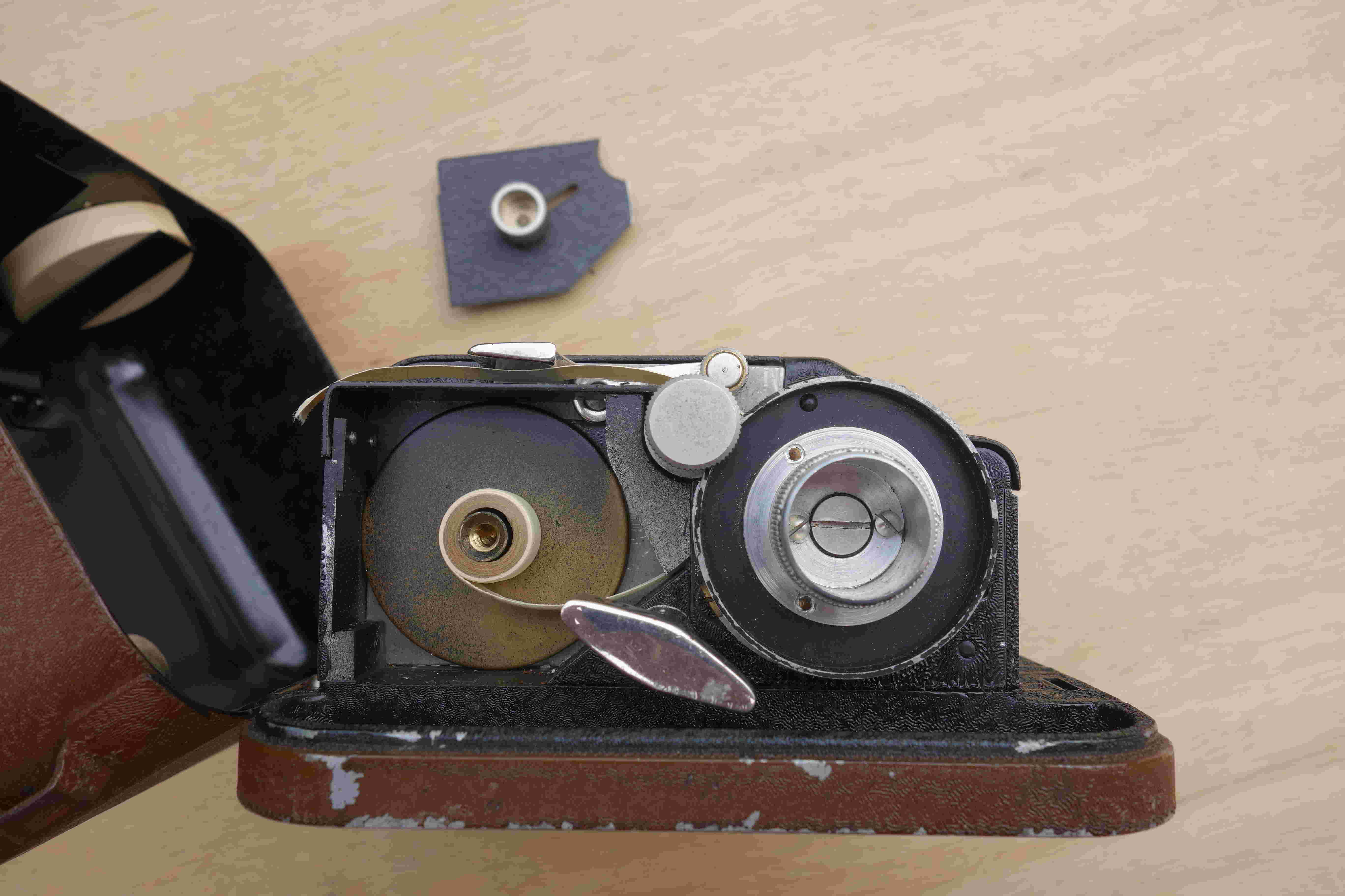
Figure 9 also shows the left side of the machine but with the paper roll protector removed. We can distinguish the roll of paper that is in use. It is inside the machine and normally it is not visible. Indeed, the location of the roller is protected by housing, which is removed in the figure and visible at the top of the image. [3] The cipher-decipher knob is visible in the middle of the figure between the type wheel and the paper roll.
 |
 |
On Jerry Proc's website, we can see the prototype of the C-36: the C-35. We can also see some pages from the C-36 M2 manual (cf. 7.3). One of the pages shows the lubrication points. A priori they are the same on the original model.
Footnotes:
- [1] The original C-36 manual has not been recovered. No image shows the use of the machine on the operator's knee. However, the 1944 manual of the M-209 shows this use (Ilord).
- [2] The number next to the K is hidden because a number ends with a space encrypted by a K and therefore the K cannot correspond to a number.
- [3] The perspective effect makes the cover protecting the paper roll appear smaller than it actually is.
2.6 Different variants of the C-36
We have noted that the lugs present on the C-36 are fixed (they are mobile on the M-209). The author was surprised to discover that their configuration could differ from one machine to another. An encryption network must have machines with the same lug configuration.
A document from ARCSI [1] (Fabreguettes 2002) specifies that it was possible to change the bars of the C-36 and therefore to change the configuration of the lugs. Then again, because the operation was complex, it was not carried out by the operator but was reserved for technicians working in repair shops.
Here is a summary of the configurations encountered:
- Configuration A is that observed on a machine owned by a collector who wished to remain anonymous (Mr. X). Its particularity is to have two bars that each have two lugs [2]. All other configurations only have one lug per bar. Mr. X also specified that he had bought his machine from a German and that it had belonged to a Wehrmacht officer who captured it in 1940.
- Configuration B is that observed on a machine belonging to the collection of the 8th RT (Régiment de Transmission = Signal Regiment) of Mt Valérien. It is also given as an example in the work by Mr. Muller (Muller 1983).
- Configuration C is that described by a German cryptanalyst working during World War II (TICOM IF-107 1944). It is also that of the C-35 (Hagelin and Kahn 1994), the prototype of the C-36.
- Configuration D is that given as an example of a configuration described in the ARCSI document (Fabreguettes 2002).
Table 2 provides the details for each of these configurations.
The ARCSI document indicates that the change in configuration was made in the 1950s. But was this change made during WWII? Anyway, was there one or more lug configurations at that time? This is an important question and we will answer it in this Web Page.
Hagelin designed the C-36 at France’s request but also tried to sell it to other countries. Jerry Proc’s website tells us that Finland at least acquired this machine but as a variant of the French model: the C-362A (Proc). This model is newer and more secure than the French C-36. Indeed, the squirrel cage now has bars with mobile lugs (only one lug per bar instead of two for the C-38/M-209). Hagelin also allegedly sold C-36s to the Swedish Navy (Torbjörn 2005). Finally, Hagelin tried to sell his machine to the Italians and the Americans, but without success (Wikipedia).
Footnotes:
- [1] ARCSI (Association des Réservistes du Chiffre et de la Sécurité de l'Information) is a French association in the field of cryptography and digital security.
- [2] Having two lugs per bar generates the overlap phenomenon. For the bars with two lugs, the activity of either one or both of the wheels involved will still contribute only one kick for that bar since the bar acts as one tooth of a gear. The amount of overlap (i.e., the number of displaced bars with two effective lugs) must be subtracted from the total number of lugs actuated at a given setting to ascertain the actual total key. A priori having overlaps improves security because the same key can hide the fact that certain pins are active or not active.
Table 2: Different lug configurations of C-36
       Config. A   Config B.   Config. C   Config D
       (Mr. X)  (Mt Valérien) (C-35/TICOM) (ARCSI)
Wheels 1 2 3 4 5   1 2 3 4 5   1 2 3 4 5   1 2 3 4 5
Bars
25             x           x           x           x
24             x           x           x           x
23             x           x           x           x
22             x           x           x           x
21             x           x           x           x
20             x           x           x           x
19             x           x           x           x
18             x           x           x           x
17             x           x           x           x
16             x           x           x           x
15             x           x         x             x
14             x           x         x             x
13           x           x           x           x
12           x           x           x           x
11           x           x           x           x
10           x           x           x           x
 9           x           x           x           x
 8           x           x           x           x
 7           x         x           x             x
 6         x           x           x           x
 5         x           x           x           x
 4         x           x           x           x
 3       x           x           x           x
 2       x     x     x           x           x
 1     x       x   x           x           x
Wheels 1 2 3 4 5   1 2 3 4 5   1 2 3 4 5   1 2 3 4 5
Total  1:2:3:7:14  1:2:4:6:12  1:2:4:8:10  1:2:3:7:12
Overlaps:   2           0           0           0
References
- Fabreguettes, J-P, 2002. Étude de la machine ŕ chiffrer C36, Bulletin de l’ARCSI, N°30.
- Muller, A, 1983. Le Décryptement, Presses Universitaires de France.
- Hagelin, C. W., Kahn, D., 1994. THE STORY OF THE HAGELIN CRYPTOS, Cryptologia, 18:3, 204-242, DOI: 10.1080/0161-119491882865
Web Links
- Bouchaudy, J-F, The cipher machine M-209. (link).
- Ilord, B, Bob Lord's Crypto Museum, M-209 Manual. (link).
- Proc, J, Hagelin C-35 and C-36. (link).
- Proc, J. Hagelin C-362. (link).
- Torbjörn, A, 2005. The Hagelin C-35/C-36. (cf. Wikipedia reference).
- Wikipedia, 2021. C-36 (cipher machine). link). This web site cite the Torbjörn’s site and provides a link through the web.archives.org site.